
Sartorius YSB01CI-X Series Manual de usuario

98647-003-53
Installation Instructions | Betriebsanleitung
Sartorius Filling Module YSB01CI-X..
and Filling PCB YDO0 C-X for
Use with the Combics CIXS Indicator
Sartorius Dosierbox YSB01CI-X..
und Dosierplatine YDO0 C-X
in Verbindung mit Combics-EX Indicator CIXS
Filling PCB in IP65-protected Housing with utputs
for Controlling Valves
Dosierplatine im IP65-Gehäuse mit Ausgängen
zur Steuerung von Ventilen

2
English - page
Deutsch - Seite 0

3
General View of the Equipment
1 Filling box
2 Manufacturer’s ID label
(on the back panel of the filling module)
3 Seal ring
4 Connecting cable for the indicator
5 Protective caps covering bore holes
provided for cable glands
Cables:
– For controlling 2 valves
(coarse/fine filling)
– For connecting signal transmitters;
e.g., foot switches
6 Ground/earth terminal
7 Ventilation valve
1
2
3
4
5
6
7

4
Contents Warnings and
Safety Precautions
3General View of the Equipment
4Warnings and Safety Precautions
5Intended Use
6Installation
6Installing the Filling Module
12 Installing the Filling PCB
15 Specifications
15 Accessories
16 Documents for Hazardous Areas
The following symbols are used in
these instructions:
§indicates required steps
$indicates steps required only under cer-
tain conditions
> describes what happens after you have
performed a particular step
– indicates an item in a list
!indicates a hazard
Equipment Supplied
– Filling module with filling PCB
or
– Filling PCB for CIXS3 indicator
– The equipment complies with Directive
94/9/EC for use in the following hazardous
areas: Zone 1 and 2 (gases) and Zone 20, 21
and 22 (dusts).
– When used in hazardous area in which com-
bustible dusts are present, the IP65 protection
of the equipment must be intact. For this
reason, it is essential that installation and
maintenance are performed with extreme care;
in particular:
– Make sure all seals are installed
– bserve all instructions carefully when
installing the cover
– Tighten all fastening screws
– Tighten all cable glands and make sure they
are installed in accordance with instructions
– The filling module must be disconnected from
power before the housing is opened. To do
this, unplug the power cord on the equipment
that powers the filling module (e.g., Combics
indicator).
Connect the filling module only to equipment
approved for this purpose by Sartorius.
– There is an M4 threaded rod on the filling
module for connecting a grounding conductor.
Make sure to ground (earth) the filling module.
– The filling module may be operated only within
an ambient temperature range of –20°C to
+40°C (–4°F to +104°F).
– When used in a hazardous area in which
combustible dusts are present, clean the filling
module regularly to prevent excessive build-up
of dust. In a Zone 20 hazardous area, the max-
imum permissible dust layer thickness is 5 mm.
– Installation, maintenance and repair work
should be performed only by service techni-
cians trained and authorized by Sartorius.
Any work that is not performed in accordance
with these instructions and acknowledged
technical standards will result in forfeiture of
the approval for use in hazardous areas, and of
all claims under the manufacturer’s warranty.
– Make sure to observe all national laws and
regulations governing the use of such equip-
ment. Ask your supplier for information on the
legal regulations applicable in your country.

5
Intended Use
The filling PCB and filling module are
designed for controlling two intrinsically
safe filling valves:
– Coarse filling valve
– Fine filling valve
and two status indicators:
– “Filling active”
– “Filling active, weight within tolerance limits”
in the following hazardous areas:
Zones 1, 2, 20, 21 and 22.
The filling module permits input of up
to 3 signals through a hand or foot switch.
The filling PCB and filling module process
signals from the control output lines (C M1)
of the CIXS3 indicator.
The inputs and outputs meet the requirements
for intrinsically safe electrical apparatus
(see EX-approval under “Documents
for Hazardous Areas”).
Note:
If the YD 03C-X filling PCB was ordered separately, it must be installed in the CIXS3
indicator. Installation, maintenance and repair work should be performed only by service
technicians trained and authorized by Sartorius. bserve all warnings and safety
precautions included in these instructions.
Coarse/ Status Signal
fine valves indicator transmitter
YD 03C-X filling PCB
on C M1 of the indicator
CIXS3 indicator
Coarse/ Status Signal
fine valves indicator transmitter
YSB01CI-X.. filling module
4 outputs/ 3 inputs
4 control lines,
3 inputs from C M1
on the indicator
CIXS3 indicator

6
Installation
!bserve all warnings and safety precautions.
!Make sure to disconnect the equipment from power before beginning installation.
Always make sure the equipment is disconnected from power before performing any
installation, maintenance or repair work.
!Work that affects the IP protection must be carried out with extreme care.
!Any installation work that does not conform to the instructions in this manual will result
in forfeiture of all claims under the manufacturer’s warranty.
!Please use extreme caution when performing work on cable glands.
!Unused bore holes must be covered by protective caps.
Note:
Installation, maintenance and repair work should be performed only by service technicians
trained and authorized by Sartorius. Any work that is not performed in accordance with
these instructions and acknowledged technical standards will result in forfeiture of the
approval for use in hazardous areas, and of all claims under the manufacturer’s warranty.
Installing the Filling Module
Connecting the Filling Module to the
CIXS indicator
§Make sure to disconnect the CIXS3 indicator from
power before opening the indicator housing.
§Remove the protective cap from the bore hole on the
indicator.
Note:
The seal and nut are required for installing the cable.
§Guide the cable with the pre-installed cable gland
through the bore hole.
Note:
Place the seal from the protective cap between the
cable gland and the housing.
§Install cable gland on the housing
in accordance with industry standards.

7
§Please use extreme caution when performing work
on the cable gland.
Make sure IP protection is intact and the cable con-
nection withstands strain. Attach the nut from the
protective cap on the inside of the housing. Use a
torque wrench and tighten the cable gland to 3 Nm.
§Connect valves, hand switches or foot switches to the
corresponding strips in the filling module according
to the drawings included with the EX-approval
(see “Documents for Hazardous Areas”).
§Install the cable that connects the filling module,
filling PCB and indicator by plugging the male
connectors into strip ST6.
§Attach ferrules to the ends of the 9 wires in the
connecting cable and connect the wires to the
terminal strip LV5 on the main PCB of the indicator
in accordance with the color coding (see diagram).

8
Installing a Cable with Cable Gland in the Filling
Module
§To open the filling module, remove the four screws
from the cover and remove the cover.
Note:
Make sure the seal rings are in place before you re-
close the filling module housing. Replace any defec-
tive seal rings.
§Remove the protective cap from the bore hole on
the indicator.
Note:
The seal and nut are required for installing the
cable.
§Guide the cable with the pre-installed cable gland
through the bore hole.
Note:
Place the seal from the protective cap between the
cable gland and the housing.
§Install cable gland on the housing
in accordance with industry standards.
§Please use extreme caution when performing work
on the cable gland.
Make sure IP protection is intact and the cable con-
nection withstands strain.
Attach the nut from the protective cap on the inside
of the housing. Use a torque wrench and tighten the
cable gland to 3 Nm.

9
Installing a Cable Gland on a Cable
§Remove the threaded fastener from the cable gland.
§Remove the other threaded fastener (4), the strain-
relief (6) and the seal (5) from the cable gland and
place them on the end of the cable.
§Remove the casing from a section of the cable end.
The shielding (1) must have secure contact with
the clamps (2). Fold back approx. 3-4 mm of the
shielding over the strain relief.
§Expose enough of the wires (3) in the cable to
permit connection within the terminal.
Important:
Do not touch the PCB.
§Cover wires with isolating tubing.
§Route the cable through the cable gland.
§Make sure the shield is in contact with the clamps.
§Reassemble all components of the cable gland on
the cable and tighten it as far as it will go.
§Unused wires must be cut short (no longer than
15 mm from the end of the cable gland) and
isolated (e.g., with shrink-down tubing).
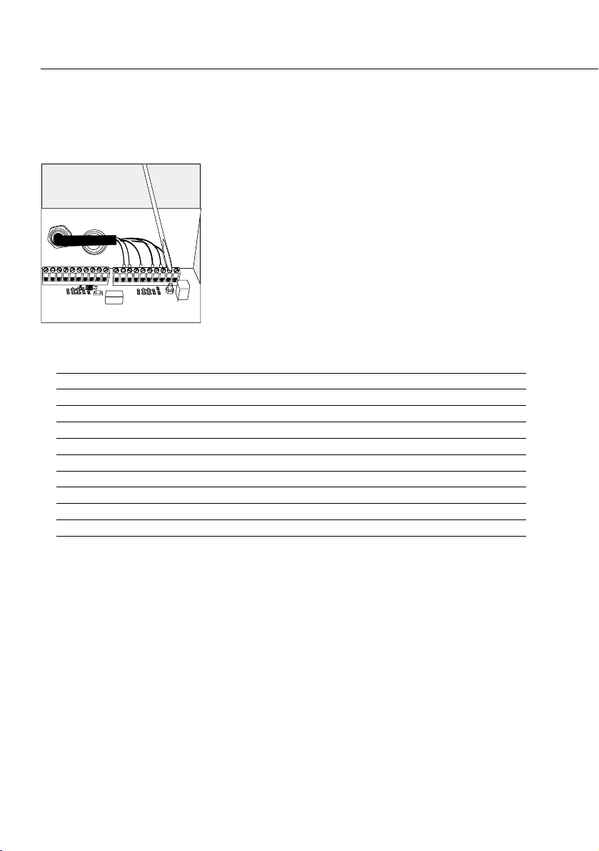
§Connect the wires to the terminals.
10
Fastening the Cable Ends for Connecting
Coarse/Fine Valves or Accessories to the Filling
Module
§Attach the cable ends (from the cable installed with
a cable gland) to terminal strips LV1 and LV4 on the
filling PCB and tighten the screws.
LV1: Signal name Signal name
Pin 1: Switch_1 Pin 1: In_Tolerance_elec.*
Pin 2: GND Pin 2: GND_ext.
Pin 3: Coarse flow Pin 3: Filling active_elec.*
Pin 4: GND Pin 4: GND_ext.
Pin 5: Fine flow Pin 5: In_tolerance
Pin 6: GND Pin 6: GND
Pin 7: Coarse flow_ elec.* Pin 7: Filling_ active
Pin 8: GND_ext. Pin 8: GND
Pin 9: Fine flow_ elec.* Pin 9: Switch_2
Pin 10: GND_ext. Pin 10: Switch_3
Switches 1 to 3 are universal inputs. These are activated through settings in the operating
menu.
Note:
For drawings detailing the connection of coarse/fine filling valves or signal transmitters,
see “Documents for Hazardous Areas.”
* The signals are electrically isolated from the filling PCB.
11
Este manual sirve para los siguientes modelos
1
Tabla de contenidos
Idiomas:
Otros manuales de Unidad de control de Sartorius

Manuales populares de Unidad de control de otras marcas

Festo
Festo Compact Performance CP-FB6-E Manual de lista de piezas

Elo TouchSystems
Elo TouchSystems DMS-SA19P-EXTME Manual de usuario

JS Automation
JS Automation MPC3034A Manual de usuario

JAUDT
JAUDT SW GII 6406 Series Guía rápida

Spektrum
Spektrum Air Module System Manual de usuario

BOC Edwards
BOC Edwards Q Series Manual de usuario


