Samson EB 5206 EN Series Manual de servicio

Translation of original instructions
EB 5206 EN
Type 5343 Safety
Temperature Monitor
(STM)
Type5344 Temperature
Regulator (TR)
Type 5345 Safety
Temperature Limiter (STL)
Type5347 Double
Thermostat (TR/STL)
Type5348 Double
Thermostat (TR/STM)
Type5349 Double
Thermostat (STM/STL)
Thermostats
Type5343 · Type5344 · Type5345
Type5347 · Type5348 · Type5349
Edition October 2017

Note on these mounting and operating instructions
These mounting and operating instructions assist you in mounting and operating the device
safely. The instructions are binding for handling SAMSON devices.
ÎFor the safe and proper use of these instructions, read them carefully and keep them for
later reference.
ÎIf you have any questions about these instructions, contact SAMSON‘s After-sales Service
Department (aftersalesser[email protected]).
The mounting and operating instructions for the devices are included in
the scope of delivery. The latest documentation is available on our website
at www.samson.de > Service & Support > Downloads > Documentation.
Denition of signal words
Hazardous situations which, if not avoided,
will result in death or serious injury
Hazardous situations which, if not avoided,
could result in death or serious injury
Property damage message or malfunction
Additional information
Recommended action
DANGER
!
WARNING
!
NOTICE
!
Note
Tip
2 EB 5206 EN

Contents
EB 5206 EN 3
1 General safety instructions.............................................................................4
2 Design and principle of operation ..................................................................5
2.1 Typetesting ....................................................................................................5
2.2 Technical data ...............................................................................................6
2.3 Mounting accessories.....................................................................................9
3 Installation..................................................................................................10
3.1 Mounting position........................................................................................10
3.2 Contact thermostat .......................................................................................11
3.3 Mounting the thermowell ..............................................................................11
3.3.1 Wall mounting with the capillary tube to the thermowell..................................12
3.3.2 Mounting on tanks or in pipes.......................................................................12
4 Electrical connection ....................................................................................14
5 Operation...................................................................................................15
5.1 Temperature regulator (TR)............................................................................15
5.2 Safety temperature monitor (STM) .................................................................15
5.3 Safety temperature limiter (STL) .....................................................................15
7 Lead sealing................................................................................................16
6 Dimensions in mm.......................................................................................16
8 EU declarations of conformity ......................................................................20

4 EB 5206 EN
General safety instructions
1 General safety instructions
For your own safety, follow these instructions concerning the mounting, start up, and opera-
tion of the thermostat:
−The thermostat is to be mounted, started up or operated only by trained and experienced
personnel familiar with the product.
According to these mounting and operating instructions, trained personnel refers to
individuals who are able to judge the work they are assigned to and recognize possible
dangers due to their specialized training, their knowledge and experience as well as
their knowledge of the applicable standards.
−Upon installation of the electric cables and connecting the device, observe the VDE
regulations as well as the regulations of your local power supplier. Make sure all
electrical connections are installed only by trained and experienced personnel.
To avoid damage to any equipment, the following also applies:
−Proper shipping and storage are assumed.
The device with a CE marking fullls the requirements of the Directives 2014/30/EU and
2014/30/EU, 2014/35/EU and 2011/65/EU.
The EU declarations of conformity are included in the Appendix of these instructions.
Note
EB 5206 EN 5
Design and principle of operation
2 Design and principle of oper-
ation
The thermostats are equipped with a
changeover contact. When the thermostat is
triggered, the connection between connec-
tions 1 and 2 are interrupted and the con-
nections 1 and 4 are connected (see Fig.5
on page14).
Safety temperature monitor (STM)
A snap-action switch in the STM is triggered
when the temperature at the temperature
sensor rises above the adjusted set point.
When the temperature falls below the set
point by approximately 8K, the switch re-
turns to its original position.
The contact opens or closes when the tem-
perature at the temperature sensor falls be-
low –20°C. It automatically closes or opens
again when the temperature at the tempera-
ture sensor rises above –20°C.
The STM is triggered when the capillary tube
breaks.
Temperature regulator (TR)
The snap-action switch is triggered when the
temperature at the temperature sensor rises
above the adjusted set point. When the tem-
perature falls below the set point by approxi-
mately 4K, the switch returns to its original
position.
Safety temperature limiter (STL)
The snap-action switch is triggered and
locked when the temperature at the tempera-
ture sensor rises above the adjusted set
point. When the temperature falls below the
set point by approximately 10%, the
snap-action switch can be unlocked manual-
ly.
The contact opens or closes when the tem-
perature at the temperature sensor falls be-
low –20°C. It automatically closes or opens
again when the temperature at the tempera-
ture sensor rises above –20°C.
The contact opens or closes when the system
fails. It is not possible to unlock the device.
2.1 Typetesting
The thermostats are tested by the German
Technical Inspectorate (TÜV) according to
DINEN14597.
Type DIN register number
5343 STW1209
5344 TR1208
5345 STB1207

6 EB 5206 EN
General safety instructions
2.2 Technical data
Single thermostats: Type5343 (STM), Type5344 (TR), Type5345 (STL)
Double thermostats: Type5347 (TR/STL), Type5348 (TR/STM), Type5349 (STM/STL)
Permissible ambient temperature
Transportation and storage –30 to +80°C
Service Max. 80°C
Max. pipe temperature when
mounted as a contact
thermostat
Max. 120°C
Degree of protection IP 54 according to EN60529
Cable entry M20x1.5 cable gland, suitable for 6 to 12mm cable diameter
Minimum switching capacity AC/DC = 24V, 100mA
Maximum switching capacity
Temperature regulator (TR),
safety temperature monitor
(STM)
With 230VAC +10% NC contact: 16A (2.5); cos φ = 1 (0.6)
NO contact: 6.3A (2.5); cos φ = 1 (0.6)
With 230VDC +10% NC contact: 0.25A
NO contact: 0.25A
Safety temperature limiter
(STL)
With 230VAC +10% NC contact: 16A (2.5); cos φ = 1 (0.6)
Signal contact: 2A (2.5); cos φ = 1 (0.4)
With 230VDC +10% NC contact: 0.25A
Signal contact: 0.25A
Inuence of mean ambient
temperature based on the set point
A shift of the switching point arises when the ambient temperature at the
knob and at the capillary tube deviates from the calibration ambient tem-
perature of +22°C:
Higher ambient temperature g Lower switching point
Lower ambient temperature g Higher switching point
This inuence is minimized by temperature compensation.
Connection Spring-cage terminals, 0.75 to 2.5mm² wire cross-section
Materials
Bottom section of the housing PA (reinforced)
Housing cover ABS with window (PMMA)
Temperature sensor, capillary
tube Cu (copper)
Weight Single thermostat approx. 0.225kg · Double thermostat approx. 0.45kg
Compliance · 1)
1) No EAC compliance for Type5349

EB 5206 EN 7
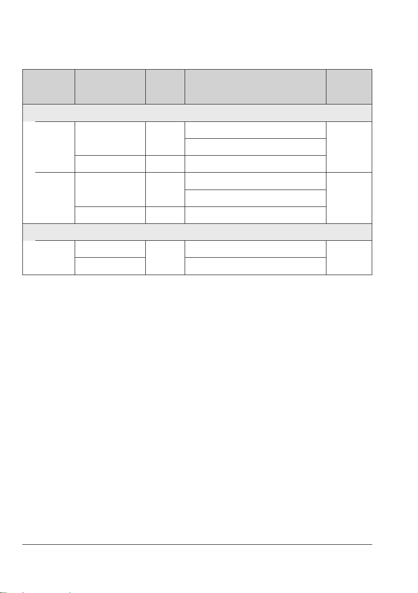
General safety instructions
Type Set point range
Switch-
ing dif-
ferential
Switching point accuracy
Max.
medium
temperature
Safety temperature monitors (STM)
5343-1 0 to 60°C 8K
Range: 0 to 25 °C 0K –8.5K
85°CRange: 25 to 35 °C 0K –6.0K
Range: 35 to 60 °C 0K –8.5K
5343-2 40 to 100°C 8K Range: 40 to 100 °C 0K –8.5K 125°C
5343-3 70 to 130°C 8K Range: 70 to 130 °C 0K –8.5K 155°C
5343-4 35 to 95°C 8K Range: 35 to 95 °C 0K –8.5K 120°C
Temperature regulators (TR)
5344-1 0 to 120°C 3K Range: 0 to 80 °C +7.2K –7.2K 145°C
Range: 80 to 120 °C +3.6K –3.6K
5344-2 20 to 150°C 4K Range: 20 to 106 °C +7.8K –7.8K 175°C
Range: 106 to 150 °C +3.9K –3.9K
Safety temperature limiters (STL)
5345-1 70 to 130°C 8K Range: 70 to 130 °C +8.5K –8.5K 155°C
5345-2 30 to 90°C 8K Range: 30 to 90 °C 0K –8.5K 115°C
Double thermostats (TR/STL)
5347-1 TR: 0 to 120°C 3K Range: 0 to 80 °C +7.2K –7.2K
145°CRange: 80 to 120 °C +3.6K –3.6K
STL: 70 to 130°C 8K Range: 70 to 130 °C 0K –8.5K
5347-2 TR: 0 to 120°C 3K Range: 0 to 80 °C +7.2K –7.2K
115°CRange: 80 to 120 °C +3.6K –3.6K
STL: 30 to 90°C 8K Range: 30 to 90 °C 0K –8.5K
8 EB 5206 EN
General safety instructions
Type Set point range
Switch-
ing dif-
ferential
Switching point accuracy
Max.
medium
temperature
Double thermostats (TR/STM)
5348-1 TR: 0 to 120°C 3K Range: 0 to 80 °C +7.2K –7.2K
145°CRange: 80 to 120 °C +3.6K –3.6K
STM: 70 to 130°C 8K Range: 70 to 130 °C 0K –8.5K
5348-2 TR: 0 to 120°C 3K Range: 0 to 80 °C +7.2K –7.2K
125°CRange: 80 to 120 °C +3.6K –3.6K
STM: 40 to 100°C 8K Range: 40 to 100 °C 0K –8.5K
Double thermostats (TR/STM)
5349-1 STM: 70 to 130°C 8K Range: 70 to 130 °C 0K –8.5K 145°C
STL: 30 to 90°C Range: 30 to 90 °C 0K –8.5K
EB 5206 EN 9
General safety instructions
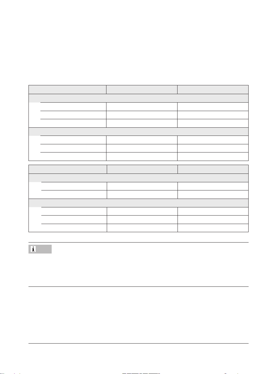
2.3 Mounting accessories
Thermowells
The thermostat is supplied without a thermowell. The following thermowells are available for
single and double thermostats as accessories:
Thermowell for single thermostat Max. pressure at 150°C Order no.
Nickel-plated brass · CuZn (2.0401)
100x8mm 48bar 1400-9844
150x8mm 48bar 1400-9845
200x8mm 48bar 1400-9846
CrNiMo steel (1.4571)
100x8mm 88bar 1400-9848
150x8mm 88bar 1400-9849
300x8mm 88bar 1400-9850
Thermowell for double thermostat Max. pressure at 150°C Order no.
Nickel-plated brass · CuZn (2.0401)
100 x (2x 8) mm 48bar 1400-9901
150 x (2x 8) mm 48bar 1400-9851
CrNiMo steel (1.4571)
100x15mm 48bar 1402-0340
150x15mm 48bar 1400-9853
300x15mm 48bar 1400-9854
The scope of delivery of the thermowell includes:
−A clip to fasten the capillary tube to the thermowell (see section3.3.1)
−A small metal plate with screw to attach the thermostat to the thermowell (see sec-
tion3.3.2)
Strap
Strap for mounting the contact thermostat (15 to 100mm
pipe diameter)
Order no.: 1400-9865
Note

10 EB 5206 EN
Installation
3 Installation
Inadequate protection against water jets
through insufcient sealing.
−Do not remove the seals in the housing
(1) and on the set point adjuster of the
temperature regulator (4). See Fig.1.
−The thermostat must only be operated
with an inserted seal (6). See Fig.1.
Risk of thermostat malfunction due to
measuring uid escaping upon breakage of
the capillary tube.
−Do not bend or cut the capillary tube.
−Do not use a smaller bending radius
than 5mm.
Table 1: Properties of the measuring uid
Dangerous reaction No
Ignition temperature 375°C
Water hazard Class 1
Slightly contaminating
Toxicological specications
Irritant No
Health hazard No
Toxic No
3.1 Mounting position
Contact thermostat
The thermostat must not be suspended with
the bottom of the housing (containing the
sensor) facing upwards.
Thermostat with thermowell
The valve can be mounted in any desired
position.
NOTICE
!
NOTICE
!
1Thermostat
2Sensor
3Capillary tube
4Set point adjuster (TR only)
5a Spring for unlocking (STL only)
6 Seal
Necessary seals for degree of
protection IP54
TR
1
2
3
5a
4
6
Fig.1: Necessary seals for degree of protection IP54
Este manual sirve para los siguientes modelos
6
Tabla de contenidos
Otros manuales de Termostato de Samson


Manuales populares de Termostato de otras marcas

EWELLY
EWELLY EW-181 Manual de usuario

Prolon
Prolon T1100 Instrucciones de instalación

Computherm
Computherm Q20 Manual de usuario

Heatmiser
Heatmiser neoStat Manual de usuario

Aube Technologies
Aube Technologies TH111GFCI-NP 240 VCA Manual de usuario

Mars
Mars HEAT CONTROLLER IR Wireless Thermostat Manual de usuario


