S4 Tech DOG Manual de usuario

S4 Tech Inc
0
MOBILE DIGITAL OBSERVATION
GUARD (DOG) USER MANUAL
Version 1.0
Feb. 1, 2010

S4 Tech Inc
1
Table of Contents
Mobile DOG System Description.............................................................................................................3
Setting up the Mobile Base Station .......................................................................................................... 4
Opening the Unit...................................................................................................................................5
Connecting Power.................................................................................................................................6
AC Power..........................................................................................................................................6
DC Power..........................................................................................................................................7
Powering Up the Mobile DOG.............................................................................................................8
Setting up the Rugged Remote Cameras (up to 1500 ft)........................................................................10
Connecting the Cameras to the Mobile DOG Base Station................................................................11
Using the External PTZ Joystick........................................................................................................13
Alignment of Cameras........................................................................................................................14
Removing a connection from a Remote Camera Unit (Figure 17).....................................................15
DVR Setup.............................................................................................................................................. 15
Power Down .......................................................................................................................................17
Password Setting................................................................................................................................. 17
Set the Date/Time............................................................................................................................... 17
Set Recording Mode ...........................................................................................................................18
Configure Motion Detection, Video Loss, and Alarms......................................................................18
Exporting Video Clips to CD .............................................................................................................19
Changing/Focusing a Lens .....................................................................................................................20
Maintenance............................................................................................................................................ 21
Cleaning the Filters.............................................................................................................................21
Changing the Fuses.............................................................................................................................21
Terminating CAT-5 Cable......................................................................................................................22
Troubleshooting......................................................................................................................................22
Contact Info............................................................................................................................................24
Replacement Parts ..................................................................................................................................24
Appendix A: Video Motion Detection Setup Tips................................................................................. 25
Table of Figures
Figure 1: Mobile DOG Base Station ........................................................................................................3
Figure 2: Mobile DOG System and Options............................................................................................ 4
Figure 3: Rear panel of the Base Station..................................................................................................5
Figure 4 Open Case and Caution Area. ...................................................................................................5
Figure 5: The Front or User Panel............................................................................................................6
Figure 6: Connecting AC Power...............................................................................................................7
Figure 7: Connecting DC Power...............................................................................................................7
Figure 8: Power on the Unit......................................................................................................................8
Figure 9: Turn off the Battery Alarm. ......................................................................................................8
Figure 10: Powered Up Monitor View.....................................................................................................9
Figure 11: Prep CAT-5 for Camera Connection.....................................................................................10
Figure 12: CAT-5 Cable through Watertight Connector Body..............................................................10
Figure 13: Complete CAT-5 Camera Connection.................................................................................. 11
Figure 14: Connect Camera to Base Station........................................................................................... 12
Figure 15: Live Camera Image on Monitor............................................................................................12
Figure 16: External PTZ Joystick........................................................................................................... 13

S4 Tech Inc
2
Figure 17: Connecting External PTZ......................................................................................................13
Figure 18: Checking the PTZ Channel...................................................................................................14
Figure 19: Aligning a Camera................................................................................................................ 14
Figure 20: Remove CAT-5 Camera Connection....................................................................................15
Figure 22: DVR Interface Panel.............................................................................................................16
Figure 21: Main Menu Screen - Labeled................................................................................................ 16
Figure 23: Power Down Menu Screen....................................................................................................17
Figure 24: Plug in USB Storage Device.................................................................................................19
Figure 25: Changing//Focusing a Lens...................................................................................................20
Figure 26: Cleaning the Filters...............................................................................................................21
Figure 27: Changing Fuses.....................................................................................................................21
Figure 28: CAT-5 Termination Wiring..................................................................................................22
NOTE: THIS MANUAL SERVES AS A GUIDE TO RAPIDLY SETTING UP AND USING
THE DOG SYSTEM. SPECIFIC DETAILS OF THE DVR OPERATION ARE DEFERRED
TO THE ENCLOSED DVR USER MANUAL WHICH COMES PACKAGED WITH EACH
KIT.

S4 Tech Inc
3
Mobile DOG System Description
The Mobile Digital Observation Guard (DOG) from S4 Tech is a rapidly deployable self-contained
security and surveillance system designed for the CENTCOM operational environment. The Mobile
DOG is a standalone security system that has been designed to be portable, rugged, cost effective, easy
to install in the field, and easy to maintain.
The Mobile DOG system is an integrated package containing an embedded H.264 Digital Video
Recorder (DVR) unit capable of simultaneously displaying live video, recording live video, and
performing motion detection for the attached cameras. The system takes power from any 110-
240VAC 50/60Hz AC power source or any 10-30 DC power source, and distributes video, power, and
data signals to the remote rugged low-light camera units up to 1500ft away using standard CAT-5
cable with standard connectors. This distribution is accomplished via the built-in DOG Video Power
Data (VPD) unit and specialized circuitry at the remote cameras. The power and control signals for
DOG PTZ cameras can also be sent over the same CAT-5 cables.Video data is collected, displayed,
and recorded at the DVR. Motion detection, user triggered alarms, and storage parameters are all set up
using the DVR screen menus and panel buttons.
Installation of the rugged low-light camera modules only requires mounting the camera unit to a wall
or pole and connecting a single standard CAT-5 cable with an RJ-45 connector through the weather
resistant connector on the camera module. The Mobile DOG Base Station is integrated into a rugged
transport case as seen is shown in the figure below. An active thermostat based cooling system (as seen
from the filtered air ports in the figure below) allows the Base Station to operate in temperatures up to
50 deg C.
Figure 1: Mobile DOG Base Station
The Mobile DOG system with its various options and configurations is shown in Figure 2 below.
Option kits for the DOG system are:
•IR Illuminator Kit - both visible and IR illumination to over 300m with adjustable flood light
and spotlight modes via removable filter lenses for all four cameras.
•PT Kit – Pan/Tilt units that connect to the remote rugged low-light cameras and IR illuminators
to provide remote controlled pan/tilt capability for both day and nighttime surveillance of large
areas. No additional cables are required to add the Pan/Tilt unit to a camera. It operates using
the same signal/power CAT-5 cable as a DOG Camera.
•Wireless Kit – with over 200m LOS range that uses the same standard 1500m CAT-5
connections as the standard DOG system.
•PTZ Camera Kit – Pan/Tilt/Zoom cameras that connect via the same CAT-5 infrastructure, and
provide very low light capability with 10x zoom and the option to mount a thermal camera
also.

S4 Tech Inc
4
•Thermal Camera Kit – small form factor thermal cameras that run off the DOG CAT-5
infrastructure and can be integrated with the DOG PTZ unit.
Figure 2: Mobile DOG System and Options
Setting up the Mobile Base Station
MAKE SURE THE MONITOR IS POWERED DOWN IF YOU ARE PLANNING ON OPERATING
THE MOBILE DOG BASE STATION WITH THE LID CLOSED. FAILURE TO DO SO MAY RESULT
IN TEMPERATURE DAMAGE TO THE MONITOR.
The connection panel on the back of the case as seen in the figure below is the main interface for all
power and camera connections. The connectors labeled “CAMERA 1” through “CAMERA 4” are
covered RJ-45 jacks used with the DOG’s CAT-5 cable infrastructure. The BNC connector labeled
“VIDEO OUT” is used with standard 75ohm coax cable to send the Mobile Base Station video to any
NTSC compatible monitor. The AC input is a standard IEC receptacle labeled “110-240VAC” and can
take any AC input within that range at 50 or 60 Hz. The DC input is labeled “12-24VDC” and uses the
special interface cable provided in the cable bin as discussed below. The DC input will tolerate an
input range of 10 to 30 volts DC. The connector labeled “Ethernet” is an RJ-45 jack used for
connecting the DOG to a LAN or the WEB for networking applications.
WARNING

S4 Tech Inc
5
Figure 3: Rear panel of the Base Station.
Opening the Unit
To open the Mobile Base Station, undo the two latches on the outside of the case and lift up the lid as
shown in the figure below.
As seen in the figure below, there is a gap between the open lid and the case. Do not stick fingers in
this gap to pick up the unit or for any other reason, as injury could result.
With the built in monitor the lid is relatively heavy, so please close the lid carefully while guiding it
with your hand. DO NOT PUSH THE LID DOWN UNGUIDED AS IT WILL SLAM WITH SOME
FORCE.
Figure 4Open Case and Caution Area.
WARNING

S4 Tech Inc
6
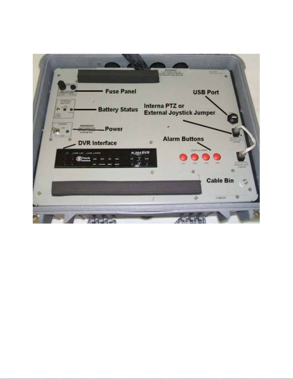
The user panel as seen in the figure below contains all the buttons and interfaces necessary for the
complete operation of the Mobile Base Station.
Figure 5: The Front or User Panel.
There is a small cable bin built into the user panel marked “CABLES” as seen in the figure above.
This bin contains power cables and fuses. Simply unscrew the finger-screw and lift the lid up to
expose the cable bin.
Connecting Power
Place the Mobile DOG Base Station on the table or desk where it is to be used. Connect either the AC
or DC power cable as described below.
AC Power
The Mobile DOG has built in surge protection and battery backup, so the use of an external surge
protector or battery backup is not necessary. To connect the mobile DOG to AC power simply remove
the AC power cord from the cable bin. Make sure the power switch is in the off position and then plug
in the cable as shown in the figure below.

S4 Tech Inc
7
Figure 6: Connecting AC Power
DC Power
The Mobile Base Station can be powered with a DC input range of 10-30 volts. This allows standard
12VDC batteries or 24VDC military batteries to be used. Remove the DC cable from the cable bin on
the user panel. Connect the back end to your DC source using terminal blocks, adapters, or other
appropriate low voltage connections. Make sure the power switch is off and attach the front end
connector to the DC input on the back panel of the Mobile Base Station as shown in the figure below.
Figure 7: Connecting DC Power

S4 Tech Inc
8
Powering Up the Mobile DOG
To power up the mobile dog after the power source is connected, simply flip on the power switch as
shown in the figure below.
Figure 8: Power on the Unit.
There is a battery alarm to indicate that the mobile dog has lost power and is running on the backup
battery. The battery may last from 5 to 20 minutes depending on charge state and conditions, and is
simply meant to allow for a smooth power down.
DO NOT RUN THE MOBILE DOG WHILE ON BATTERY BACKUP, AS THE BATTERY CAN DRAIN
AND RESULT IN AN UNSAFE POWER DOWN OF THE UNIT. WHEN POWER IS LOST AND THE
BATTERY MODE KICKS ON, EXECUTE A PROPER POWER DOWN PROCEDURE.
To disable the audible battery alarm flip the switch as shown in the figure below.
Figure 9: Turn off the Battery Alarm.
WARNING

S4 Tech Inc
9
Once the unit powers up and finishes booting, a blank quad channel display will show on the screen as
seen in the picture below.
Figure 10: Powered Up Monitor View.
Tabla de contenidos
Manuales populares de Sistema de seguridad de otras marcas

EDM
EDM Solution 6+6 Wireless-AE Manual de usuario

Highway Safety Group
Highway Safety Group EA401 Manual de usuario

Siren
Siren LED GSM Manual de usuario

Detection Systems
Detection Systems 7090i Instrucciones de montaje

Se-Kure Controls
Se-Kure Controls MicroMini SK-4841 Manual de usuario

Siemens
Siemens FDM273 Manual de usuario