RuggedCom RuggedServer RS910 Manual de usuario

RuggedCom Inc. I30 Whitmore Road, Woodbridge, Ontario, Canada L4L 7Z4
Tel: (905) 856-5288 I Fax: (905) 856-1995 IToll Free: (888) 264-0006
RuggedS
RuggedSRuggedS
RuggedServer
ervererver
erver
RS9
RS9RS9
RS91
11
10
00
0
2-Port Serial Device Server with up to 3 Ports Managed
Ethernet Switch
Installation Guide
www.ruggedcom.com

2
2007 RuggedCom Inc. All rights reserved Rev100
Federal Communications Commission
Radio Frequency Interference Statement
This equipment has been tested and found to comply with the limits for a Class A digital device
pursuant to Part 15 of the FCC Rules These limits are designed to provide reasonable protection
against harmful interference when the equipment is operated in a commercial environment This
equipment generates, uses and can radiate radio frequency energy and, if not installed and used in
accordance with the instruction manual, may cause harmful interference to radio communications
Operation of this equipment in a residential area is likely to cause harmful interference in which
case the user will be required to correct the interference at his expense
Trademarks:
Ethernet is a trademark of Xerox Corporation
RuggedSwitch, RuggedRated, ROS and eRSTP are trademarks of RuggedCom® Inc
Caution
This product contains a laser system and is classified as a “CLASS 1 LASER PRODUCT”
Use of controls or adjustments or performance of procedures other than those specified herein
may result in hazardous radiation exposure This product contains no user serviceable parts
Attempted service by unauthorized personnel shall render all warranties null and void
Should this device require service see the “Warranty” section of this installation guide
Important
This unit should be installed in a restricted access location where access can only be gained by
service personnel or users who have been instructed about the reasons for the restrictions
applied to the location and about any precautions that shall be taken; and access is through the
use of a tool or lock and key, or other means of security, and is controlled by the authority
responsible for the location

3
2007 RuggedCom Inc. All rights reserved Rev100
Table of Contents
1Product Overview ............................................................................................................................... 5
1.1 Functional Overview ................................................................................................................... 5
1.2 Feature Highlights ...................................................................................................................... 5
1.3 RS910 Front Panel Description .................................................................................................. 6
1.4 RS910 Bottom Panel Description................................................................................................ 7
2Installation........................................................................................................................................... 8
2.1 Din Rail Mounting....................................................................................................................... 8
2.2 Power Supply Wiring and Grounding ......................................................................................... 9
2.3 Failsafe Output Wiring.............................................................................................................. 12
2.4 RS232 Console Port Wiring ...................................................................................................... 13
3Serial Ports ........................................................................................................................................ 14
4Ethernet Ports ................................................................................................................................... 18
4.1 RJ45 Ethernet Ports .................................................................................................................. 18
4.2 Fiber Optic Ethernet Ports........................................................................................................ 19
4.3 Ethernet Panel Description ....................................................................................................... 19
5Technical Specifications ................................................................................................................... 21
5.1 Operating Environment............................................................................................................. 21
5.2 Power Supply Specifications ..................................................................................................... 21
5.3 Failsafe Relay Specifications .................................................................................................... 21
5.4 Serial Ports................................................................................................................................ 22
5.5 Ethernet Ports............................................................................................................................ 23
5.6 Communication Standards ........................................................................................................ 23
5.7 Mechanical Specifications......................................................................................................... 24
6Type Tests.......................................................................................................................................... 25
6.1 IEC 61850-3 Type Tests ............................................................................................................ 25
6.2 IEEE 1613 Type Tests ............................................................................................................... 26
6.3 IEC Environmental Type Tests.................................................................................................. 26
7Warranty ........................................................................................................................................... 27

4
2007 RuggedCom Inc. All rights reserved Rev100
Table of Figures
Figure 1 - RS910 Front Panel Description ................................................................................................. 6
Figure 2 - RS910 Bottom Panel Description............................................................................................... 7
Figure 3 - RS910 DIN Rail Mounting ......................................................................................................... 8
Figure 4 - RS910 Power Supply Inputs....................................................................................................... 9
Figure 5 - DC Power supply wiring and grounding diagram ................................................................. 10
Figure 6 - Dielectric Strength Testing....................................................................................................... 11
Figure 7 - RS910 Failsafe Output Relay................................................................................................... 12
Figure 8 - RS232 Female DCE pin-out ..................................................................................................... 13
Figure 9: Fiber Serial Interface (ST Connector) ..................................................................................... 14
Figure 10: DB9 Port pin-out...................................................................................................................... 15
Figure 11: RJ45 Port pin-out..................................................................................................................... 16
Figure 12: Conceptual recommended RS485 wiring diagram ............................................................... 17
Figure 13 - RJ45 Ethernet port pin-out.................................................................................................... 18
Figure 14: 10FL ST connector.................................................................................................................. 19
Figure 15: 100FX MTRJ connector ......................................................................................................... 19
Figure 16: 100FX ST connector ............................................................................................................... 19
Figure 17: 100FX LC connector............................................................................................................... 19
Figure 18: 100FX SC connector ............................................................................................................... 19
Figure 19: Ethernet panel LED description ............................................................................................ 20
Figure 20 - Mechanical Specifications ...................................................................................................... 24
Table of Tables
Table 1 - Status LEDs................................................................................................................................... 6
Table 2 – RJ45 Ethernet port pin-out....................................................................................................... 18
Table 3 – RJ45 Ethernet port 9 LED description .................................................................................... 20
Table 4 - Operating Environment............................................................................................................. 21
Table 5 - Power Supply Specifications...................................................................................................... 21
Table 6 - Failsafe Relay Specifications...................................................................................................... 21
Table 7: Copper Port Specification........................................................................................................... 22
Table 8: Fiber Optic Port Specification.................................................................................................... 22
Table 9: Ethernet Ports - Copper Specifications ..................................................................................... 23
Table 10: Ethernet Ports – Fiber Optic Specifications........................................................................... 23
Table 11 - Communication Standard Compliance .................................................................................. 23
Table 12 - Mechanical Specifications........................................................................................................ 24
Table 13 - IEC 61850-3 Type Tests ........................................................................................................... 25
Table 14 - IEEE 1613 Type Tests .............................................................................................................. 26
Table 15 - Environmental Type Tests....................................................................................................... 26

5
2007 RuggedCom Inc. All rights reserved Rev100
1 Product Overview
1.1 Functional Overview
The RuggedServerTM RS910 is an industrial hardened serial server with an integrated, fully
managed, Ethernet switch, designed to o erate reliably in electrically harsh and climatically
demanding environments. The RS910 can be configured with 2 serial orts
(RS485/RS422/RS232/fiber) and/or u to 3 Ethernet orts (co er or fiber). The RS910 is able to
interconnect multi le ty es of intelligent electronic devices (IEDs) that have different methods of
communications. Using the RS910 results in fewer connectivity devices and also extends the
useful life of existing legacy IEDs.
1.2 Feature Highlights
•Serial Device Server
oTransmit serial data over an IP network
o2 Serial Port Interfaces
oRS485/RS422/RS232 (DB9 or RJ45 connectors)
oSerial Fiber Interface (ST) o tion
oSu ort for Modbus TCP, DBP 3, TIN serial rotocols
oBaud rates u to 230 kb s
oRaw socket mode allows conversion of any serial rotocol
oPoint-to- oint and multi- oint modes
oConverts Modbus RTU to Modbus; Multi le Modbus masters
oConverts DNP 3.0 to DNP over UDP/TCP
•Ethernet Ports:
oIntegrated fully Managed Ethernet Switch
oU to 3 Fast Ethernet Ports (co er and/or fiber)
oSu orts many ty es of fiber (Multimode, Singlemode)
oMulti le connector ty es (ST, MTRJ, LC, SC)

6
2007 RuggedCom Inc. All rights reserved Rev100
1.3 RS910 Front Panel Description
Failsafe Relay Power Port
Ports 1 & 2
RS485/422/232
Serial
Or
Serial over Fiber
Ports 3 & 4
10/100Base-T
or
100Base-F
Or
10Base-FL
Port 9
10/100Base-T
or
100Base-F
Power & Alarm
Figure 1 - RS91 Front Panel Description
Status LED Colour Activity Comments
Power LED Green Solid Power On
Alarm LED Red Solid Alarm condition exists
Table 1 - Status LEDs

7
2007 RuggedCom Inc. All rights reserved Rev100
1.4 RS910 Bottom Panel Description
Failsafe Relay
Console Port
Power
Port
Chassis
Ground
Optional Din-Rail
Mounting Bracket
Figure 2 - RS91 Bottom Panel Description

8
2007 RuggedCom Inc. All rights reserved Rev100
2 Installation
2.1 Din Rail Mounting
An o tional DIN rail mounting bracket is available for the RS910. The figure below details mounting
instructions for the standard 1” DIN Rail.
Figure 3 - RS91 DIN Rail Mounting
9
2007 RuggedCom Inc. All rights reserved Rev100
2.2 Power Supply Wiring and Grounding
2.2.1 AC Power Supply Wiring and Grounding
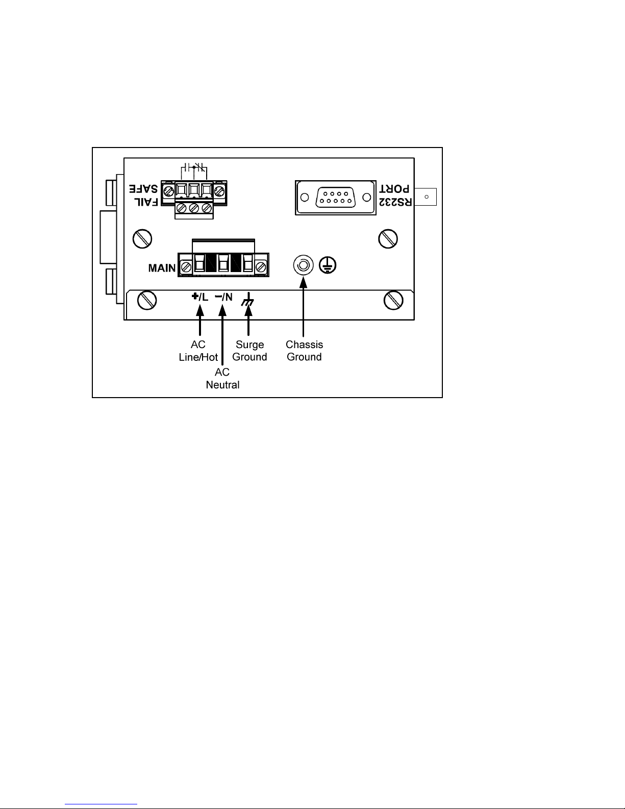
Figure 4 - RS91 Power Supply Inputs
The RS910 AC ower su ly in uts should be connected as follows:
1. +/L should be connected to AC Line/Hot.
2. -/N should be connected to AC Neutral.
3. Surge Ground should be connected to the Chassis Ground via a braided cable or other
a ro riate grounding wire. Surge Ground is used as the ground conductor for all surge
and transient su ression circuitry internal to the unit.
4. Chassis Ground must be connected to the AC ground terminal.
NOTES:
1. Equi ment must be installed according to the a licable country wiring codes.
2. All line-to-ground transient energy is shunted to the Surge Ground terminal. In cases
where users require the in uts to be isolated from ground, remove the ground braid
between Surge and Chassis Ground. Note that all line-to-ground transient rotection
circuitry will be disabled.

10
2007 RuggedCom Inc. All rights reserved Rev100
2.2.2 DC Power Supply Wiring and Grounding
Figure 5 - DC Power supply wiring and grounding diagram
The RS910 low voltage DC ower su ly features reverse olarity rotection and dual inde endent
in uts. The latter feature allows the connection of two DC sources with the same nominal voltage
to rovide redundant ower su ly in uts.
The RS910 DC ower su ly in uts should be connected as follows:
1. Connect to the DC in uts according to the olarity markings on the unit.
2. Surge Ground should be connected to the Chassis Ground via a braided cable or other
a ro riate grounding wire. Surge Ground is used as the ground conductor for all surge
and transient su ression circuitry internal to the unit.
3. Chassis Ground must be connected to the rotective earth.
NOTES:
1. Equi ment must be installed according to the a licable country wiring codes.
2. All line-to-ground transient energy is shunted to the Surge Ground terminal. In cases
where users require the in uts to be isolated from ground, remove the ground braid
between Surge and Chassis Ground. Note that all line-to-ground transient rotection
circuitry will be disabled.
Otros manuales para RuggedServer RS910
1
Tabla de contenidos
Otros manuales de Servidor de RuggedCom

RuggedCom
RuggedCom RuggedServer RS400 Manual de usuario

RuggedCom
RuggedCom RuggedWireless RS920W Manual de usuario

RuggedCom
RuggedCom RuggedWireless RS920W Manual de usuario

RuggedCom
RuggedCom RuggedWireless RS910W Manual de usuario

RuggedCom
RuggedCom RuggedServer RS416 Manual de usuario

RuggedCom
RuggedCom RuggedMC RMC30 Manual


