
RuggedCom RuggedServer RS400 Manual de usuario

RuggedServerRS400 Family
4-Port Serial Device Server with Integrated 4-Port Managed
Ethernet Switch
Installation Guide
October 14, 2009
www.ruggedcom.com
RuggedCom Inc. I300 Applewood Cres., Unit 1, Concord, Ontario, Canada L4K 5C7
Tel: 905-856-5288 I Fax: 905-856-1995 IToll Free: 1-888-264-0006

Copyright
COPYRIGHT © 2009 RuggedCom Inc. ALL RIGHTS RESERVED
Dissemination or reproduction of this document, or evaluation and communication of its
contents, is not authorized except where expressly permitted. Violations are liable for
damages. All rights reserved, particularly for the purposes of patent application or
trademark registration.
This document contains proprietary information, which is protected by copyright. All
rights are reserved. No part of this document may be photocopied, reproduced or
translated to another language without the prior written consent of RuggedCom Inc.
Disclaimer of liability
We have checked the contents of this manual against the hardware and software
described. However, deviations from the description cannot be completely ruled out.
RuggedCom shall not be liable for any errors or omissions contained herein or for
consequential damages in connection with the furnishing, performance, or use of this
material.
The information given in this document is reviewed regularly and any necessary
corrections will be included in subsequent editions. We appreciate any suggested
improvements. We reserve the right to make technical improvements without notice.
Registered Trademarks
RuggedServer™ is a trademark of RuggedCom Inc. RuggedSwitch®is a registered
trademark of RuggedCom Inc. Other designations in this manual might be trademarks
whose use by third parties for their own purposes would infringe the rights of the owner.
Contacting RuggedCom
Corporate Headquarters US Headquarters Europe Headquarters
RuggedCom Inc.
300 Applewood Cres., Unit 1
Concord, Ontario
Canada, L4K 5C7
Tel: (905) 856-5288
Fax: (905) 856-1995
Toll-free: 1 (888) 264-0006
RuggedCom
1930 Harrison St., Suite 209
Hollywood, Florida
USA, 33020
Tel: (954) 922-7938 x103
Fax: (954) 922-7984
Toll-free: 1 (888) 264-0006
RuggedCom
Unit 41, Aztec Centre,
Aztec West, Almondsbury, Bristol
United Kingdom BS32 4TD
Tel: +44 1454 203 404
Fax: +44 1454 203 403
Email: [email protected]
Technical Support
Toll Free (North America): 1 (866) 922-7975
International: +1 (905) 856-5288
Email: [email protected]
Web: www.RuggedCom.com
2
RuggedCom® RuggedServer™ RS400 Family Installation Guide rev109

Federal Communications Commission Radio
Frequency Interference Statement
This equipment has been tested and found to comply with the limits for a Class A digital
device pursuant to Part 15 of the FCC Rules. These limits are designed to provide
reasonable protection against harmful interference when the equipment is operated in a
commercial environment. This equipment generates, uses and can radiate radio
frequency energy and, if not installed and used in accordance with the instruction
manual, may cause harmful interference to radio communications. Operation of this
equipment in a residential area is likely to cause harmful interference in which case the
user will be required to correct the interference at his expense.
Caution
This product contains a laser system and is classified as a “CLASS 1 LASER
PRODUCT”.
Use of controls or adjustments or performance of procedures other than those
specified herein may result in hazardous radiation exposure. This product contains no
user serviceable parts. Attempted service by unauthorized personnel shall render all
warranties null and void.
Should this device require service see the “Warranty” section of this installation guide.
Important
This unit should be installed in a restricted access location where access can only be
gained by service personnel or users who have been instructed about the reasons for
the restrictions applied to the location and about any precautions that shall be taken;
and access is through the use of a tool or lock and key, or other means of security,
and is controlled by the authority responsible for the location.
3
RuggedCom® RuggedServer™ RS400 Family Installation Guide rev109

Table of Contents
Table of Contents
Federal Communications Commission Radio Frequency Interference Statement......................... 3
Table of Contents ............................................................................................................................ 4
1Product Overview.................................................................................................................... 5
1.1 Functional Overview..........................................................................................5
1.2 Feature Highlights .............................................................................................5
1.3 RS400 Series Description.................................................................................7
1.1.1 RS400........................................................................................................7
1.1.2 RS401........................................................................................................9
2Installation............................................................................................................................. 11
2.1 Mounting..........................................................................................................11
2.1.1 RS400......................................................................................................11
2.1.2 RS401......................................................................................................12
2.2 Power Supply Wiring and Grounding ..............................................................13
2.2.1 Power Supply - AC Input.........................................................................14
2.2.2 Power Supply – DC Inputs ......................................................................14
2.3 HIPOT (Dielectric Strength) Testing................................................................15
2.4 Failsafe Relay Outputs....................................................................................16
2.5 RS232 Console Port Wiring ............................................................................17
2.6 Serial Ports......................................................................................................18
2.6.1 4 x RS232 via DB9..................................................................................19
2.6.2 4 x RS485 via Phoenix............................................................................20
2.6.3 4 x RS232/RS485/RS422 via DB9 ..........................................................21
2.6.4 4 x RS232/RS485/RS422 via RJ-45........................................................22
2.6.5 RS485 Wiring ..........................................................................................23
2.6.6 Serial Port Transient Protection...............................................................24
2.7 Ethernet Ports .................................................................................................25
2.7.1 RJ-45 Twisted-Pair Ports.........................................................................26
2.7.2 Ethernet Port Transient Protection..........................................................26
2.7.3 Fiber Optic Ports......................................................................................27
2.8 V.90 Modem Port (Optional)............................................................................28
3Technical Specifications ....................................................................................................... 29
3.1 Operating Environment ...................................................................................29
3.2 Power Supply Specifications...........................................................................29
3.3 Failsafe Relay Specifications ..........................................................................30
3.4 Data Port Specifications..................................................................................30
3.5 Fiber Optical Specifications.............................................................................31
3.6 Type Test Specifications.................................................................................32
3.7 Physical Dimensions .......................................................................................33
3.7.1 RS400......................................................................................................33
3.7.2 RS401......................................................................................................35
4Agency Approvals................................................................................................................. 36
5Warranty................................................................................................................................ 36
4
RuggedCom® RuggedServer™ RS400 Family Installation Guide rev109

Product Overview
1 Product Overview
1.1 Functional Overview
The RuggedServerRS400 Series is an industrially hardened, serial device server with
an integrated, fully managed, Ethernet switch, designed to operate reliably in electrically
harsh and climatically demanding environments. The RS400 Series consists of the
RS400 and RS401 which are functionally equivalent differing only mechanically in
shape. Featuring an integrated 4 port serial server, a 4 port managed Ethernet switch,
and an optional v.90 modem, the RS400 Series is able to interconnect multiple types of
intelligent electronic devices (IEDs) that have different methods of communications.
Using the RS400 Series results in fewer connectivity devices (which reduces overall
system costs) and extends the useful life of existing legacy IEDs (which minimizes
capital expenditure for new equipment).
The RS400 Series provides a high level of immunity to electromagnetic interference and
heavy electrical surges typical of environments found in electric utility substations,
factory floors or in curb side traffic control cabinets. The RS400 Series meets or exceeds
a wide range of industry standards including IEC61850, IEEE1613, IEC61000-6-2,
IEEE61800-3, and NEMA TS-2. The RS400 Series also features a wide operating
temperature range of -40°C to +85°C allowing it to be installed in virtually any location.
1.2 Feature Highlights
Serial device server
Fully compliant EIA/TIA RS485, RS422, RS232 serial ports
(software selectable) - DB9, RJ-45, Phoenix style connectors
Baud rates up to 230 kbps
Point-to-point and multi-point modes
Convert Modbus RTU to Modbus TCP
Supports multiple Modbus masters
Serial IP' port redirection software to support Personal Computer (PC)
applications statistics and built-in 'sniffer' for troubleshooting
Ethernet Ports
Integrated Ethernet Switch – up to 4 ports
High performance and throughput Ethernet switching
Fully IEEE 802.3, IEEE 802.3u, IEEE 802.3x compliance
Non-blocking, store and forward switching
10/100BaseTX, 10BaseFL, 100BaseFX options
Remote Dial Up Access
Integrated v.90 modem and PPP server
Provides remote access to serial devices and Ethernet LAN
RuggedRated™ for Reliability in Harsh Environments
Immunity to EMI and heavy electrical surges
oMeets IEEE 1613 (electric utility substations)
oExceeds IEC 61850-3 (electric utility substations)
oExceeds IEEE 61800-3 (variable speed drive systems)
5
RuggedCom® RuggedServer™ RS400 Family Installation Guide rev109

Product Overview
oExceeds IEC 61000-6-2 (generic industrial)
oExceeds NEMA TS-2 (traffic control equipment)
Fully independent 2kV (RMS) isolated serial ports
40°C to +85°C operating temperature (no fans)
8 AWG galvanized steel enclosure
Universal Power Supply Options
Fully integrated power supplies (no external adaptors)
Popular low-voltage DC ranges: 12, 24 and 48 VDC
Universal high-voltage range: 88-300 VDC or 85-264 VAC
CSA/UL 60950 safety approved to +85°C
Rugged Operating System (ROS™) Features
Simple plug and play operation - automatic learning,
negotiation, and crossover detection
Integrated Cyber Security features
RSTP (802.1w) and Enhanced Rapid Spanning Tree (eRSTP™) network
fault recovery (<5ms).Quality of Service (802.1p) for real-time traffic
VLAN (802.1q) with double tagging and GVRP support
IGMP Snooping for multicast filtering
Port Rate Limiting and Broadcast Storm Limiting
Port configuration, status, statistics, mirroring, security
Management Tools
Web-based, Telnet, CLI management interfaces
SNMP v1/v2/v3
Remote Monitoring (RMON)
Rich set of diagnostics with logging and alarms
6
RuggedCom® RuggedServer™ RS400 Family Installation Guide rev109

Product Overview
1.3 RS400 Series Description
1.1.1 RS400
Serial Data Ports (RS232/RS485/RS422) Integrated 4-Port Switch
Serial Port
Indicators
DC (+) / AC (L)
DC (-) / AC (N)
Surge Ground
RS232
Console Port Normally Open
Common
Normally Closed
Ethernet Port
Indicators
Optional V.90
Modem Port
Figure 1: RS400 Top View
ITEM Activity Comments
Solid Link Established
LINK LED (Orange)
Blinking – Once per second Tx, Rx Activity
Tx LED (Orange) Blinking Tx (Transmit) Activity
Rx LED (Orange) Blinking Rx (Receive) Activity
POWER LED (Green) Solid Power On
Fault LED (Red) Solid Fault has occurred
Table 1: RS400 LED description
7
RuggedCom® RuggedServer™ RS400 Family Installation Guide rev109
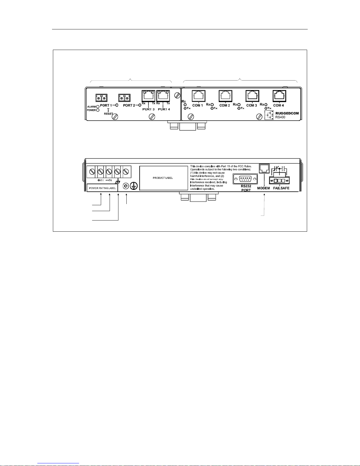
Product Overview
Serial Data Ports (RS232/RS485/RS422)
Integrated 4-Port Switch
Din Rail Mounting
Bracket
DC (+) / AC (L)
DC (-) / AC (N)
Surge Ground
Safety Ground
Stud
RS232
Console Port
Optional V.90
Modem Port
Failsafe Relay
Front
Rear
Figure 2: RS400 Front and Rear View
8
RuggedCom® RuggedServer™ RS400 Family Installation Guide rev109

Product Overview
1.1.2 RS401
DC (+) / AC (L)
DC (-) / AC (N)
Surge Ground
Normally Open
Common
Normally Closed
Failsafe Relay
RS232
Console Port
Optional V.90
Modem Port
Serial Data Ports (RS232/RS485/RS422)
Integrated 4-Port Switch
Serial Port
Indicators
Top
Bottom
Figure 3: RS401 Top and Bottom View
ITEM Activity Comments
Solid Link Established
LINK LED (Orange)
Blinking – Once per second Tx, Rx Activity
Tx LED (Orange) Blinking Tx (Transmit) Activity
Rx LED (Orange) Blinking Rx (Receive) Activity
POWER LED (Green) Solid Power On
Fault LED (Red) Solid Fault has occurred
Table 2: RS401 LED Description
9
RuggedCom® RuggedServer™ RS400 Family Installation Guide rev109

Product Overview
Figure 4: RS401 Front View
10
RuggedCom® RuggedServer™ RS400 Family Installation Guide rev109
Otros manuales para RuggedServer RS400
2
Este manual sirve para los siguientes modelos
1
Tabla de contenidos
Otros manuales de Servidor de RuggedCom

RuggedCom
RuggedCom RuggedMC RMC30 Manual

RuggedCom
RuggedCom RuggedWireless RS910W Manual de usuario

RuggedCom
RuggedCom RuggedWireless RS920W Manual de usuario

RuggedCom
RuggedCom RuggedServer RS910 Manual de usuario

RuggedCom
RuggedCom RuggedWireless RS920W Manual de usuario

RuggedCom
RuggedCom RuggedServer RS416 Manual de usuario


