
FIGURE 9 Mounting Bracket on a Flat Surface
1. Horizontal mounting 2. Vertical mounting
3. Remove the mounting bracket from the mounting surface.
4.
5.
Drill holes required for the customer-supplied mounting
hardware. Attach the mounting bracket to the flat surface using
the mounting hardware.
6. Using the mounting hardware instructions, tighten the
hardware to secure the mounting bracket.
7. Continue with Mounting the AP on page 3.
Attaching the Mounting Bracket to a Pole
1.
2.
The AP mounting bracket attaches to the AP using a captive
screw. Loosen the screw and pull up on the end of the bracket to
remove the bracket from the AP, as shown in Figure 8 on page 2.
Insert the open end of one steel clamp into two of the slots on the
mounting bracket.
NOTE: The mounting bracket can be mounted to a vertical or
horizontal pole to support the AP in the required orientation.
3.
4.
Using either of the two options shown in Figure 10, use the clamps
to attach the mounting bracket to the pole. Tighten the clamps to
3 N.m or 27 in-lbs, or per manufacturer’s specifications if the
factory-supplied clamps are not used.
If necessary, daisy-chain the other steel clamps to accommodate
larger poles.
FIGURE 10 Mounting Bracket on a Pole
1. Horizontal pole
mounting
2. Vertical pole mounting
5. Continue with Mounting the AP.
Mounting the AP
1. Snap the AP back onto the mounting bracket, as shown in Figure 11,
and use a medium flat-blade or No. 2 Phillips screwdriver to
tighten the captive screw to 1.1 N.m or 10 in-lbs to secure the
bracket to the AP, as shown in Figure 11.
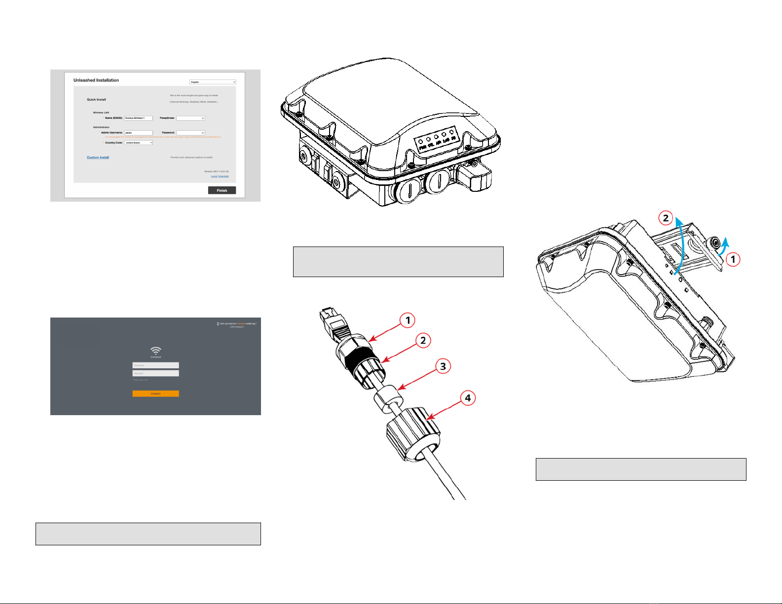
FIGURE 11 Attaching the Mounting Bracket to the AP
1. Snap the AP to the
mounting bracket
2. Tighten the captive
screw
2. Optional Step: If you also need to lock the mounting bracket to the
AP, then use an appropriately sized screwdriver to screw the
customer-supplied locking stainless steel 6-mm M3 panhead
security screw through the mounting bracket and into the AP
chassis.
CAUTION! Make sure that the customer-supplied locking stainless
steel M3 panhead security screw is no longer than 6mm. If the
security screw is longer than 6mm, it can damage the AP chassis.
FIGURE 12 Locking the Mounting Bracket to the AP
You have completed mounting the AP to the mounting bracket.
Powering the AP with DC Power
The AP can accommodate two sources of power: PoE (48V) power and
12V DC.
The AP can draw power from the Ethernet input as a Class 4 device,
providing a maximum of 18 W to the system. Alternately, power can be
supplied through a customer-provided 12V DC power supply (12V DC
preferred, 7-20V DC acceptable) that will connect to a two-pin terminal
block. The terminal block is accessible through a water-tight gland on
one end of the unit. The terminal block connection has surge and
polarity protection to protect against inserting the wrong polarity leads
into the terminal block.
NOTE: If both the PoE and DC ports are used, separate cable glands
must be used for each port. Additional cable gland (Part Number
902-0183-0000) can be be purchased.
NOTE: When both the 12V DC and the 48V PoE power are active, the AP
will prioritize the 12V DC power.
CAUTION! Ensure that the DC power source does not exceed 20V DC.
1. Install the DC power supply as described in the DC power
supply accessory installation guide.
2. Connect the power cord to a DC power source.
3. Verify that the PWR LED is a steady green.
Earth Grounding the AP
CAUTION! Make sure that earth grounding is available and that it meets
local and national electrical codes. For additional lightning protection,
use lightning rods and lightning arrestors.
NOTE: The color coding of ground wires varies by region. Before
completing this step, check your local wiring standards for guidance.
Using the factory-supplied ground wire and ground screw and washer
set, connect a good earth ground to the AP chassis ground point.
CAUTION! The EV35 includes one 9-mm stainless steel M6x1 earth
ground screw with split lock and flat washers. Make sure that any
replacement screw is no longer than 9 mm. If a screw is longer than 9
mm, it can damage the AP chassis.
Page 3 of 4
© 2022 RIVI Networks Ltd. All rights reserved. Trade
Mark No: UK00003636458 Published Jan 2022,
Part Number 800-72972-301 Rev A


 Manual de usuario")
