Rimik CP300 Manual de usuario
Instruction Manual
CP300
Cone Penetrometer


User Manual
CP300
Cone Penetrometer
Manufactured by:
Rimik
1079 Ruthven Street
Toowoomba QLD 4350
Australia
Ph. +61 438 135 215
info@rimik.com
www.rimik.com


Contents
Warranty Terms 1
Introduction 2
Controls 2
Features 3
Understanding the Menu & Parameter Settings 4
Setting Up 6
Power on, power off 6
Time & Date 6
Display Format 6
Units 6
Insertions Per Group 6
Speed Abort 7
Maximum Depth 7
Interval Size 7
Cone Size 7
Setting Up for an Insertion 7
Installing the Rimik Penetrometer Reader Software 8
Cone Wear 8
Using the CP300 8
Performing the Insertion 8
Reviewing Insertion Data 9
Clearing the Data Memory 9
Downloading Data to PC 9
Viewing Data on PC 9
Troubleshooting 10
Appendix 11
Load Calibration 11
Distance Calibration 11
Checking the Load 12
Checking the Distance 12
Battery 12
Load Cell Connection 12
Specifications 13

1. Warranty Term
Subject to the conditions set out below, Rimik warrants to the original purchaser that:
1.1 The Product will be free from defects in workmanship and materials under normal use
for a period of 1 year from the date of purchase.
2. Warranty Conditions
2.1 This warranty covers all parts found to be defective in workmanship and/or materials
during the warranty period and will be repaired or replaced at the discretion of the
manufacturer. Parts replaced will not be returned.
2.2 Rimik will not be responsible for any costs in connection with freight or postage of
replacement products or parts.
2.3 This warranty will be void and accordingly no claim of any nature whatsoever will be
enforceable against the manufacturer if the product is not installed and operated ac-
cording to the printed instructions supplied with the product or if the product is sub-
jected to abuse, neglect, misuse or an accident.
2.4 The manufacturer and/or distributor will not be liable for any incidental or consequen-
tial loss or damage arising from any cause whatsoever including but not limited to loss
or damage arising from the installation or operation of the product and/or the failure
of any part for any reason whatsoever.
2.5 There are no warranties expressed or implied except those stipulated above.
1

Introduction
The Rimik CP300 Cone Penetrometer is used to measure soil density and hardness where de-
tailed study of the data is not needed. It has been designed for use by those who only require
quick point and shoot values of soil hardness. It measures and records cone index values of the
load required to insert the cone through the soil and returns figures of the hardness of the soil.
These results can be viewed on the LCD screen or downloaded to PC via serial port over a USB
connection to the Rimik Penetrometer Reader software. Up to 500 insertions may be recorded
with depths of up to 750mm and cone index values of up to 9800kPa.
Controls
LCD Screen: The LCD Screen is a 2 x 16 character unit. All menus and data is displayed on it.
Up: The Up button moves up to the previous menu item or page of data. If already at the first
selection it will move to the last selection. It also increments numerical values.
Down: The Down button moves down to the next menu item or page of data. If already at the
last selection it will move to the first selection. It also decrements numerical values.
Cancel/Power off: The cancel button is used to enter and exit the menu, cancel a selection and
go back to the previous menu. In the Start Screen (Figure 2) it also powers the
CP300 off when held down until the unit beeps.
Enter/Power on: The Enter button is used to power the CP300 on when pressed and held down
until the unit beeps. The button also enters a chosen selection and starts an insertion from the
Start Screen.
2
Up Cancel
Down Enter
Figure 1—Front Panel
LCD Screen
LCD Screen
Figure 2—Start Screen
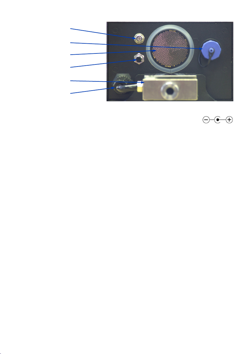
DC Power Socket: This DC Power Socket is used to connect the CP300 to an exter-
nal battery charger to recharge the internal AA batteries.
USB Connector: This USB socket is used to connect the CP300 to a PC to download insertion
data to the supplied Rimik Penetrometer Reader Software.
Transducer: The Ultrasonic Transducer is used to measure the distance to the target by send-
ing and receiving ultrasonic waves.
Reset Switch: The Reset Switch is used to force the CP300 into the power off state. Normally, it
is powered off by the Cancel/Power off button on the front panel. However because it is kept
in the power on state by the CPU and not simply a physical switch, there is a remote possibility
that in the event of some malfunction occurring, the unit can still be forced into the power off
state.
Load Cell: The Load Cell responds to the force required to insert the cone into the soil and
sends a corresponding result back for the CP300 to record.
Load Cell Connector: The Load Cell Connector is used to connect the load cell to the unit to
record the force exerted by the shaft. It should never need to be disconnected by the user.
Features
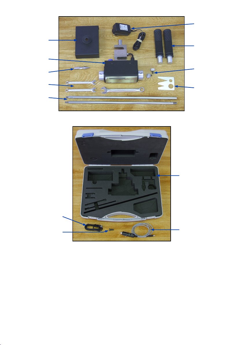
Included Items & Accessories (Figure 4)
1 x CP300
1 x Shaft (2 pieces)
1 x 130mm² ASAE Cone
1 x Target with Bush
2 x Handles
2 x Knobs for Handles
2 x 8mm Spanner
1 x 13mm Spanner
1 x ASAE Cone Wear Gauge
1 x Mains Battery Charger
1 x Serial Number Sticker, on CP300
1 x User Manual
1 x CD (user & reader software manuals)
Other Accessories (Figure 5)
Carry Case with Foam Insert
1m USB Cable
1.2m Car Charger Cable
Test Stand Bolt (used for load calibration)
3
DC Power Socket
USB Connector
Transducer
Reset Switch
Load Cell
Load Cell Connector
Figure 3 - Rear Panel
Understanding the Menu & Parameter Settings
Review Data File
This allows the user to view the data from the last 500 insertions. The CP300 displays this data
in numerical form.
Clear Data Memory
This allows the user to delete all the insertion data from the CP300.
Check Battery
The CP300 displays the battery status as a percent of total battery charge. Note that as the
batteries age over time the reading may no longer reach 100% after charging.
Target
CP300
Cone
Spanners
Shaft
Battery
Charger
Handles
Knobs for
Handles
Cone Wear
Gauge
Figure 4 - Included Items & Accessories
Carry Case
Car Charger
Cable
USB Cable
Test Stand
Bolt
Figure 5 - Optional Accessories
4

Set Clock Time & Date
Used to set the time and date since each insertion is tagged with the time and date.
Check Clock Time & Date
Used to check the time and date. If the CP300 has been off for more than about 1 or 2 weeks it
will lose its time and date.
Set Data Display Format
When reviewing insertion data on the CP300 there are two different view formats to choose
from: With depth indication and without depth indication. With depth indication turned on the
CP300 will display the depth of the data in the insertion on the top line and the corresponding
data below on the bottom line. Only 3 depths of information will display per page display re-
quiring up to 10 pages to show the complete insertion data, see Figure 6. Without depth indica-
tion the CP300 displays actual insertion data on both lines, allowing 6 depths of information to
display per page and requiring up to only 5 pages to show the complete insertion data, see
Figure 7.
Change Units Metric/Imperial
Altering the system units will change the recorded results for both pressure and depth.—KPA/
mm and PSI/Inches for metric and imperial respectively.
Change Inserts per Group
Used to alter the number of insertions in each group of data. This is useful for keeping track of
insertions within a traverse or groups of insertions by area.
Speed Abort Menu
Because the CP300 uses the ASAE standard S313.3 for measuring the soil density which speci-
fies a minimum speed of 0.2 metres per minute and a maximum speed of 2 metres per minute,
the CP300 has been included with the ability to enable speed abort alarms. The abort can be
disabled, however an audible beeping will let the user know that the cone index values may
not be an accurate representation of the actual soil density profile.
Set Maximum Depth
The Max Depth is the depth at which the CP300 will complete an insertion. It can be set up to a
maximum of 750mm in 25mm intervals.
Change Interval Size
The default interval is 25mm with 10mm, 15mm and 20mm also available.
Change Cone Size
The CP300 can use any one of the ASAE (30° face angle) or Euro (60° face angle) cone sets.
The default is ASAE 130mm². Cone sizes are selected in order of cross-sectional area.
Calibration Menu
As well as containing the settings to calibrate the load and depth measurements, the calibra-
tion menu also includes checking both the load and depth in real time. See Appendix, page 12.
5
Figure 6 - With Depth Indication Figure 7 - Without Depth Indication
Tabla de contenidos
Otros manuales de Instrumento de medición de Rimik


Manuales populares de Instrumento de medición de otras marcas


Endress+Hauser
Endress+Hauser Proline Promag 50 Especificaciones técnicas

Siemens
Siemens SITRANS F Coriolis FCT030 Manual de lista de piezas

KLINGER
KLINGER CMF V Series Manual de usuario

EXFO
EXFO FTB-2 Manual de operación y mantenimiento

Keysight
Keysight M8290A Manual de usuario

ADTEK
ADTEK MW-5 Manual de usuario