Renogy ONE M1 Manual de usuario

VERSION A1
Renogy ONE
QUICK GUIDE
M1
This Quick Guide contains important installation, operation, and maintenance instructions for Renogy
ONE M1, hereinafter referred to as “Renogy ONE”. Please read the Quick Guide carefully before using
the device.
For additional support, contact our customer service through renogy.com/contact-us/.
Renogy offers premium services worldwide:
North America US www.renogy.com CA ca.renogy.com
Asia/Pacific
AU au.renogy.com CN www.renogy.cn
JP renogy.jp KR kr.renogy.com
Europe
UK uk.renogy.com DE de.renogy.com
FR fr.renogy.com ES es.renogy.com
Scan the QR code to install the DC Home app.
For detailed instructions,
scan the QR code for the User Manual.

Table of Contents
Package Contents ..................................................................................................................01
Product Overview ...................................................................................................................02
Wiring Diagram.......................................................................................................................04
Communication Diagram........................................................................................................05
Renogy ONE Communication Architecture .......................................................................05
Energy Device Communication Connections ....................................................................05
Preparation.............................................................................................................................07
Required Tools .................................................................................................................. 07
Mounting Location ............................................................................................................. 10
Power Wiring ..........................................................................................................................12
Communication Wiring (Optional)...........................................................................................14
Load Wiring (Optional)............................................................................................................16
Mounting.................................................................................................................................20
Operation................................................................................................................................21
Activation........................................................................................................................... 21
WLAN ................................................................................................................................ 21
Pairing with App................................................................................................................. 21
Add Devices ...................................................................................................................... 22
Power On/Off..................................................................................................................... 22
Control External Loads...................................................................................................... 23
Maintenance...........................................................................................................................24

01
Package Contents
Quick Guide ×1 12V Power
Cable (5m) ×1 M2 Screws ×4 M4 Mounting
Screws ×4
VERSION A1
ST2 x 1.2 x 6.5 mm
ST4 x 2 x 13 mm
02
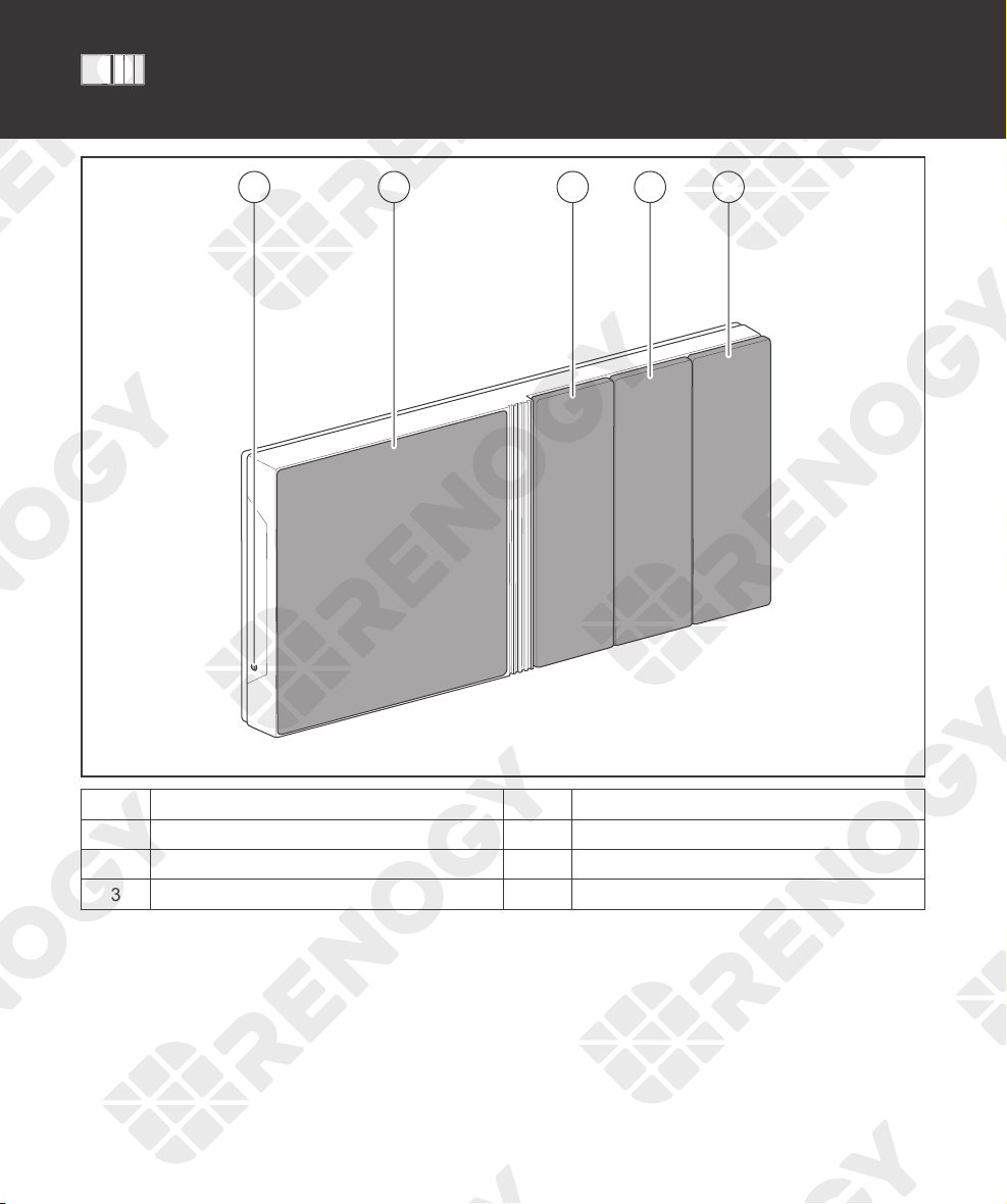
Product Overview
21 3 4 5
No. Part No. Part
1 Power Button 4 Panel Switch 2
2 Touch Screen 5 Panel Switch 3
3 Panel Switch 1

03
Product Overview
IN 1
+ -
IN 2
CAN/RS485 TYPE-C
OUT 1 OUT 2 IN 3 OUT 3
81 19 10
1 2 3 4 5 6 7 1
No. Part No. Part
1 Mounting Holes 6 IN 3 (External Load Input Terminal)
2 IN 1 (External Load Input Terminal) 7 OUT 3 (External Load Output Terminal)
3 OUT 1 (External Load Output Terminal) 8 Power Port (12V, 3.5W)
4 IN 2 (External Load Input Terminal) 9 RJ45 Port
5 OUT 2 (External Load Output Terminal) 10 Alternate Power Input Port (Type-C, 5V,
3.5W)
zPlease inspect Renogy ONE for any visible damage including cracks, dents, deformation, and other
visible abnormalities before installation.

04
Wiring Diagram
IN 1
+ -
IN 2
CAN/RS485 TYPE-C
OUT 1 OUT 2 IN 3 OUT 3
Negative
Positive
DC Load
(≤30V DC, ≤5A)
Communication
12V
Power
Supply
+
-
≤30V
Power
Supply
+
-
Devices with RV-C or
RS485 communication
zIllustrations in the Quick Guide are for reference only.
zRenogy ONE is only suitable for safe use in areas below 2,000 meters above sea level.
zThere are no user serviceable parts inside Renogy ONE. Do not disassemble or attempt to repair it.

05
Renogy ONE Communication Architecture
Cloud
Battery Charge Controller Inverter
DC-DC
Battery Charger
Other Energy
Devices
Motion Sensor
Smart Plug
Smart Relay
Window & Door
Sensor
Other Smart
Accessories
Zigbee
Wi-Fi
Renogy ONE
Wi-Fi/4G Cellular Network
Bluetooth/RS485/RV-C
To ensure good compatibility, it is recommended to use Renogy's energy devices and smart accessories.
DC
Home
App
Energy Device Communication Connections
Bluetooth
1. For devices with a built-in Bluetooth module or
an external Bluetooth module (Renogy BT-1 or
BT-2):
2. For devices connected to Renogy
Communication Hub and BT-2:
Bluetooth Bluetooth
BT-1’s
Communication
Cable
BT-2’s
Communication
Cable
Bluetooth
BT-1 BT-2
Device 1
(with Bluetooth) Device 2 Device 3
Renogy ONE
BT-2’s
Communication
Cable
Bluetooth
BT-2
Device 2Device 1 Device N
…
Communication
Hub
Ethernet CableEthernet Cable Ethernet Cable
Renogy ONE
Renogy ONE Communication Architecture Energy Device Communication Connections
Communication Diagram

06
Communication Diagram
RS485 Communication
1. For a single device with RJ45 port: 2. For devices connected to Renogy
Communication Hub:
Device
Ethernet Cable
Renogy ONE
Device 2Device 1 Device N
Ethernet Cable Ethernet Cable
...
Ethernet Cable
Ethernet Cable
Communication
Hub
Renogy ONE
RV-C Communication
For REGO devices connected with RV-C daisy chain topology:
RV-C Daisy Chain Topology
Renogy ONE
Device 2
Device 1
Device N
RV-C
Communication
Cable
RV-C
Communication
Cable
RV-C
Communication
Cable
For backbone topology, please contact our customer service through renogy.com/contact-us/.
Renogy ONE Communication Architecture Energy Device Communication Connections

07
Preparation
Required Tools
zTo prevent rework, please follow the installation steps below one after another.
Required Tools
Phillips Screwdriver (#1)
(for M2 Screws)
Phillips Screwdriver (#2)
(for M4 Screws) Insulation Tape
Skill Saw Measuring Tape Drill (1.5mm)
3
4
5
6
Required Tools Mounting Location
Otros manuales para ONE M1
3
Tabla de contenidos
Otros manuales de Sistema de seguridad de Renogy

Manuales populares de Sistema de seguridad de otras marcas


EDM
EDM Solution 6+6 Wireless-AE Manual de usuario

Highway Safety Group
Highway Safety Group EA401 Manual de usuario

Siren
Siren LED GSM Manual de usuario

Detection Systems
Detection Systems 7090i Instrucciones de montaje

Se-Kure Controls
Se-Kure Controls MicroMini SK-4841 Manual de usuario

Siemens
Siemens FDM273 Manual de usuario