8 of 21 May 5, 2011
IDT AN-727
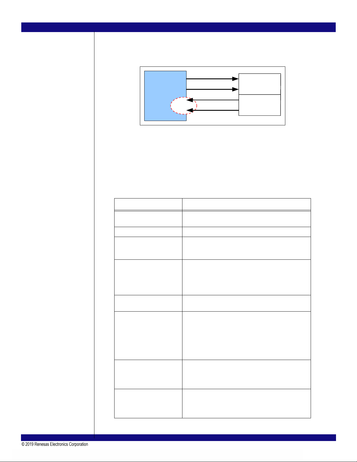
Notes logic for the receiving lane automatically inverts received data. Polarity inversion is a lane function and not
a link function. Therefore, it is possible for some lanes of link to be inverted and for others not to be
inverted.
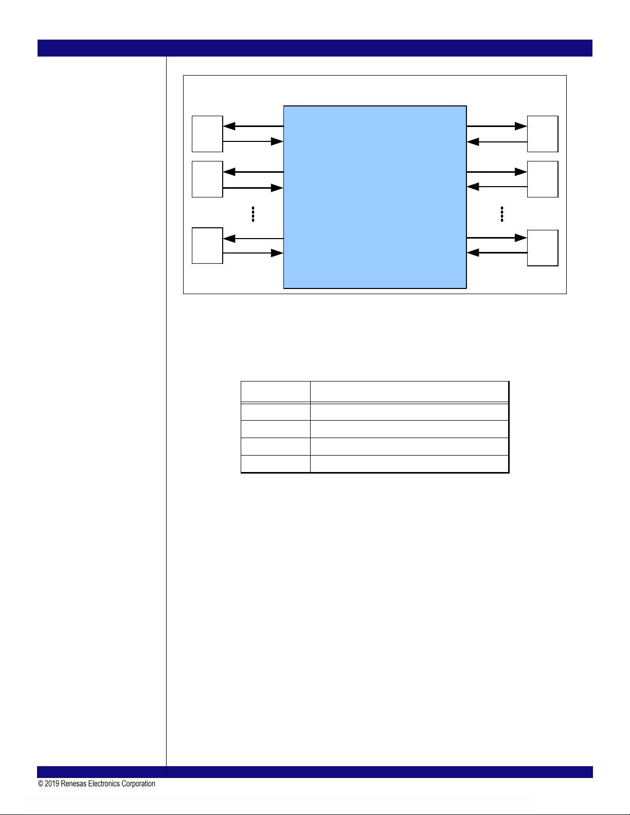
Figure 5 Polarity Inversion
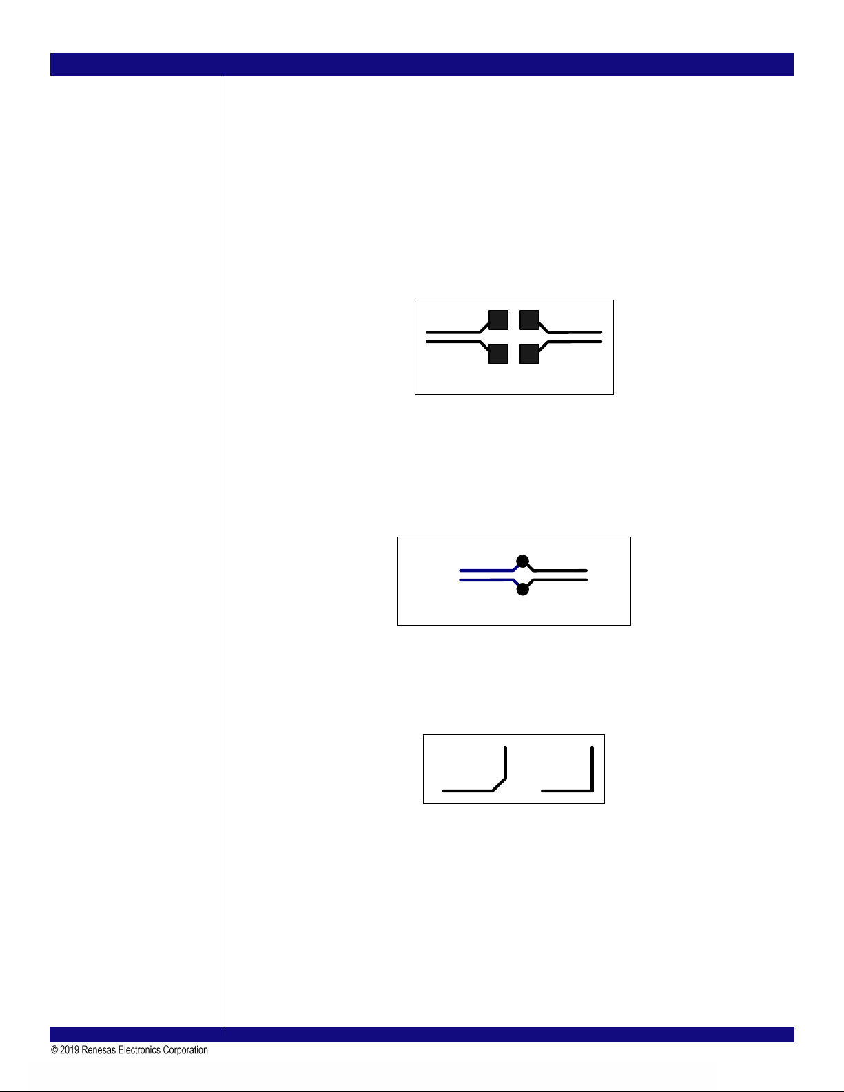
Tx Capacitors
The PCIe specification requires that each lane of the link is AC coupled between its corresponding
transmitter and receiver. The AC coupling capacitors for the PES32NT24AG2 are discrete components
located along each transmitter link on the PCB. These AC coupling capacitors allow the transmitter and
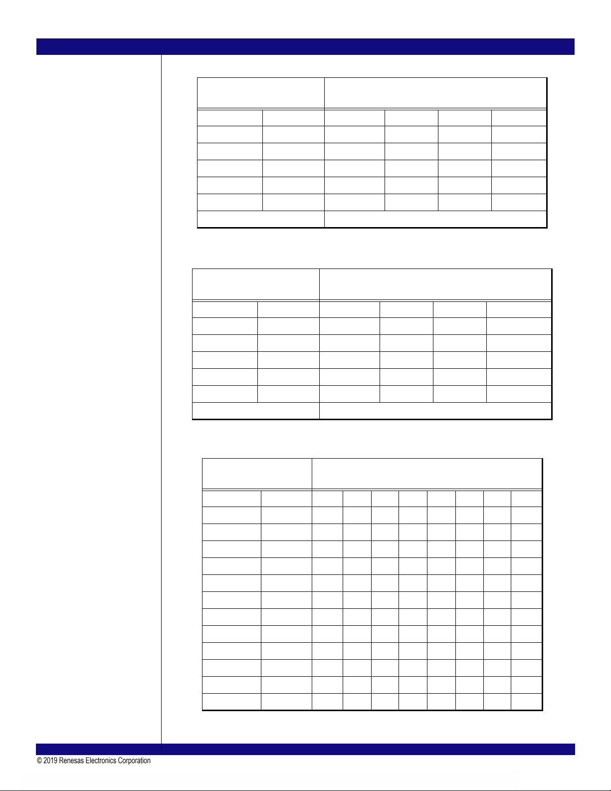
receiver on a link to be biased at separate voltages. Table 1 summarizes the guidelines for implementing
the PCIe AC coupling capacitors on a system board.
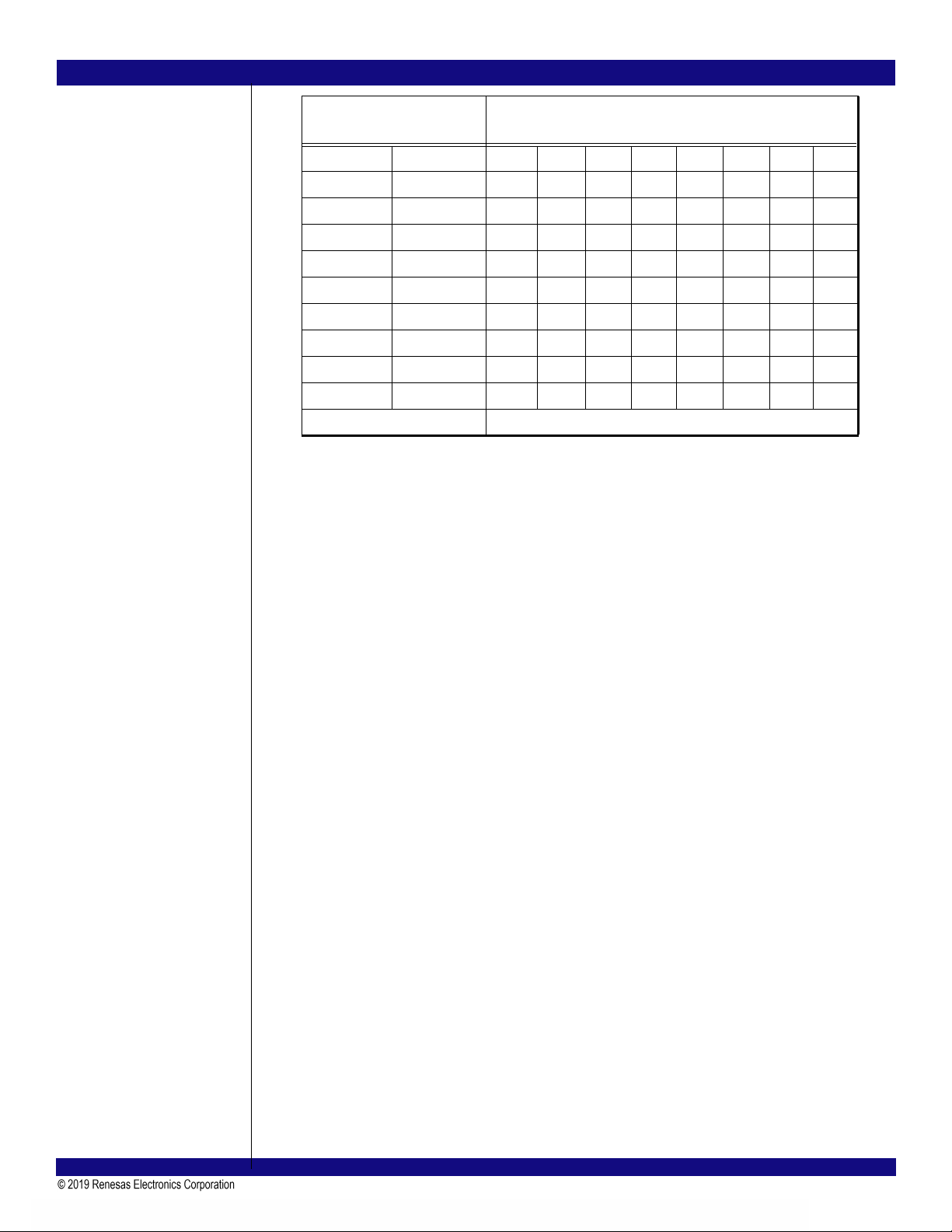
Parameter Implementation Guideline
AC Coupling AC coupling capacitors are required on the Tx pairs originating
from the PES32NT24AG2
Capacitor Value Between 75nF and 200nF
Capacitor Tolerance Specified minimum/maximum range must be met when capacitor
toleranceisconsideredalongwitheffectsduetotemperatureand
voltage
Capacitor Type Size 603 ceramic capacitors are acceptable, however, size 402
capacitors are strongly encouraged. The smaller the package
size, the less ESL is introduced into the topology. The same
package and capacitor size should be used for each signal in a
differential pair. Do not use capacitor packs for PCIe AC coupling.
Capacitor Pad Size To minimize parasitic impacts, pad sizes for each capacitor
should be the minimum allowed per PCB manufacturer.
Capacitor Placement AC coupling capacitors should be located at the same place
within the differential pair. They should not be staggered in dis-
tance from one trace of the differential pair to the other. Capaci-
tors should be placed as close to each other as possible to avoid
creating large uncoupled sections within the differential pair
traces. Relative location from one differential pair to another is
not important.
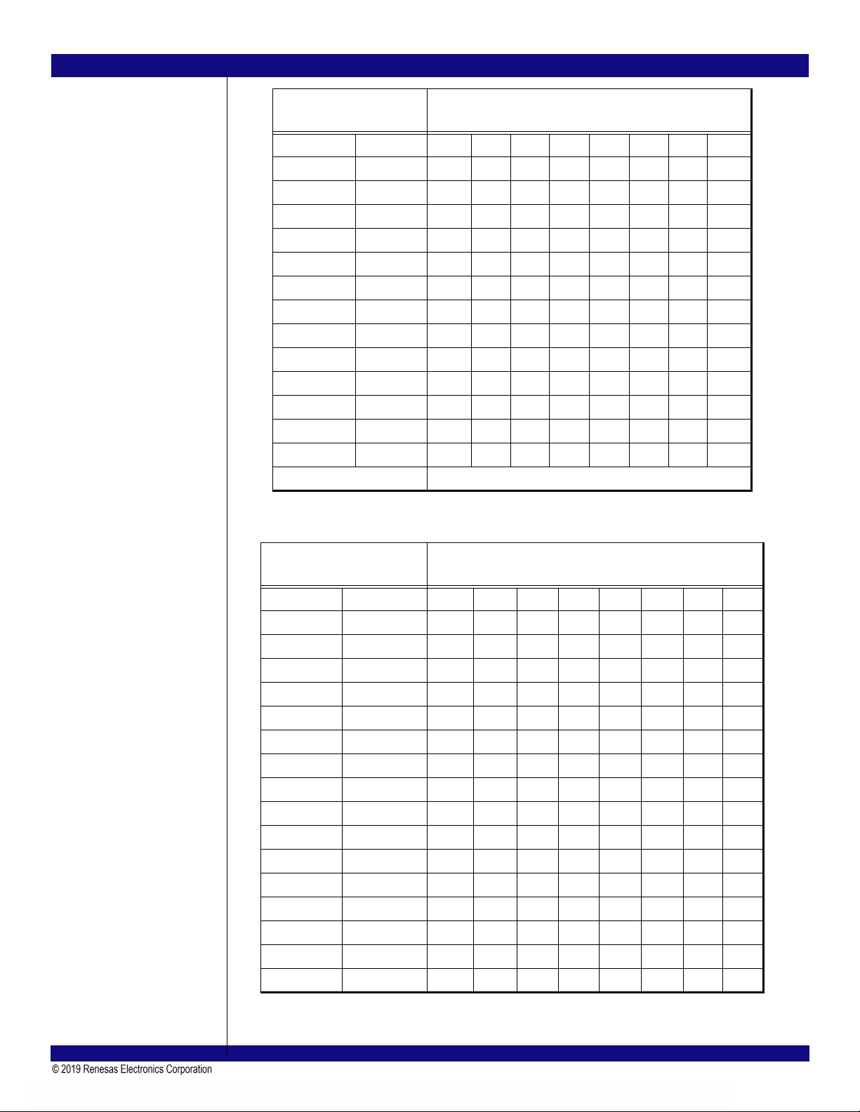
Capacitor Location –
Chip-to-Connector Routing Capacitors should be placed such that they are not located in the
center point of a trace route (for example, capacitors should be
placed next to the connector or 1/3 the distance between the con-
nector and the PES32NT24AG2.
Capacitor Location –
Chip-to-Chip Routing Capacitors should be located off-center within the interconnect
(for example, placing the capacitors next to the Rx pins of one
device is generally better than locating the capacitors in the mid-
point of the interconnect).
Table 6 PCIE Interface AC Coupling Capacitor Guidelines
PExT[n]
+
-
+
-
PExR[n]
RX
+
-
+
-
TX