Reefe DPR Manual de usuario

INSTRUCTION MANUAL
DIGITAL & ELECTRONIC
PRESSURE REGULATOR
MODEL: DPR | EPR
CODE: 28391 | 30288 | 28384 | 30271

www.reefe.com.auAscento Group Australia P: 1800 807 6042
CONTENTS
Description 3
Operating Characteristics 3
ART Function 4
APR Function 4
Technical Characteristics 4
Hydraulic Installation 5
Electronic Connection 5
Control Panel 6-7
Startup 8-9
Basic & Advanced Menu 10
Pressure Sensor Calibration 11
Warnings and Alarms 12
Warranty Information 13-14

www.reefe.com.auAscento Group Australia P: 1800 807 604 3
GENERAL
Read the instructions carefully before installing this unit. Verify the technical characteristics of the motor in
order to assure the compatibility with the device.
DESCRIPTION
EPR - Electronic Pressure Regulator
The EPR is an electronic controller for single-phase pumps up to 2.2kW with an innovative system of pressure
reduction/regulation in order to maintain a steady outlet pressure. Therefore, in addition to the typical
features of traditional electronic pump controllers: integrated non-return valve, flow sensor, accumulation
membrane, pressure gauge, indicator led-lights, dry-run protection, automatic restart system (ART). It allows
adjusting and control of the output pressure, avoiding overloads and water hammer. Ultimately, improving
the comfort and durability of the installation.
DPR - Digital Pressure Regulator
Evolving from EPR, adding to its features a digital display with instantaneous indication of current
consumption and outlet pressure since it houses current and pressure transducers inside. This device allows
separates the regulation of the outlet pressure from the cut-in pressure to improve the flexibility of the
system’s hydraulic reserve, reducing the prolongation of inactive pauses and, consequently, reducing the
number of starts of the electric pump. This independence from pressure regulation also allows operation with
a minimum dierential between the cut-in pressure (ON) and the outlet pressure (OUT). It also integrates
alarm and function registers, as well as the possibility of adjusting multiple operating parameters such as
automatic reset system, anti-flood function, start and stop delays, etc.
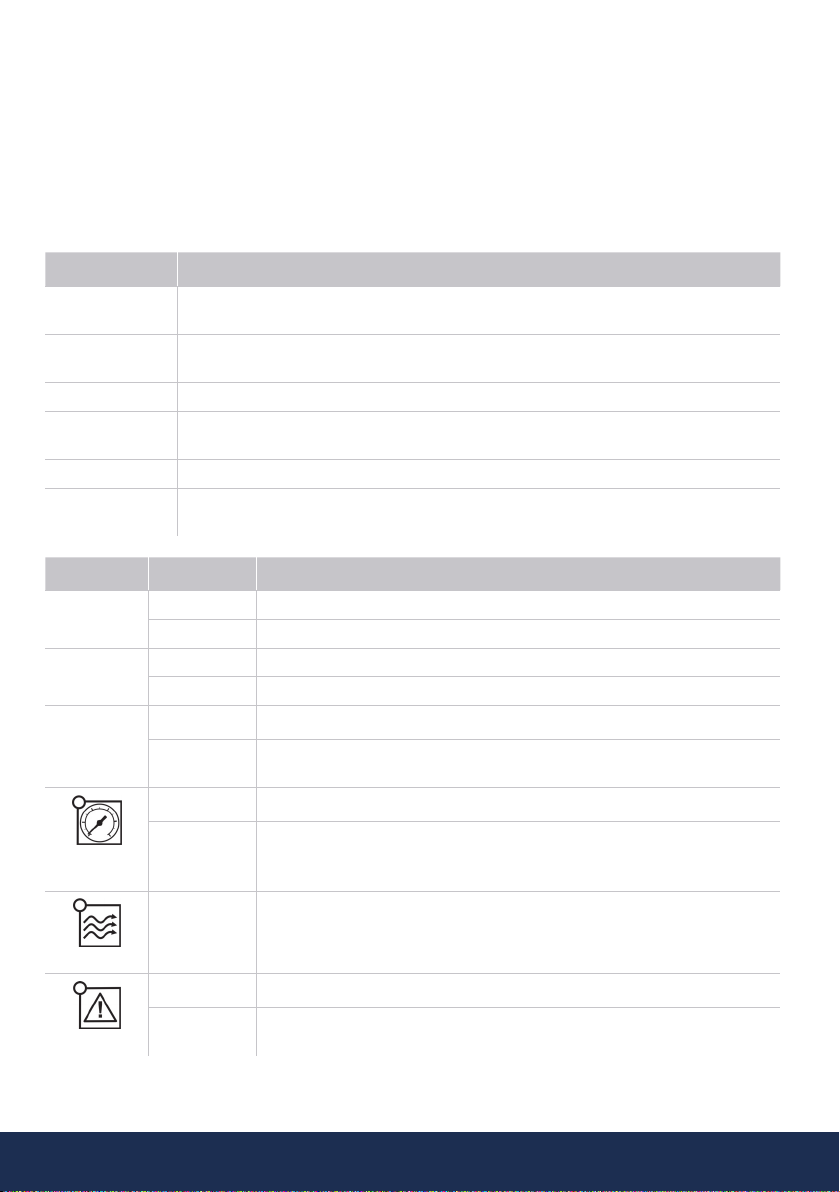
OPERATING CHARACTERISTICS
EPR DPR
Starting Pressure Depends on the adjusted outlet
pressure.
Adjustable from 0.5bar to 5.5bar
Outlet Pressure Adjustable from 2.5 bar to 6 bar
by the rear allen screw. (Refer Fig
1 and 2)
Adjustable from 2.5 bar to 6 bar
by the rear allen screw. (Refer Fig
1 and 2)
Outlet Pressure Reading Pressure Gauge Digital
Dry-running Protection Yes Yes
Over-current Protection No Yes
ART* Function Yes Yes
Manual start push button Yes Yes
Control Panel LED indicator lights and ENTER
push button
3-digit display, LED indicator lights
and 4 push buttons (up and down
arrows, amps and enter)
APR** Function Yes Yes
Anti-flooding
configuration
No Yes
Stand-by Mode No Yes

www.reefe.com.auAscento Group Australia P: 1800 807 6044
*ART FUNCTION (AUTOMATIC RESET TEST)
When the device has stopped, the pump by the intervention of the dry-running protection system, the ART
tries after 5 minutes to re-start the pump in order to restore the water supply. After this first attempt is
performed, it will attempt every 30 minutes.
In the DPR, this function can be activated in the ADVANCED MENU. The number of attempts can be set
(1-48) and also the span of the attempt (10-40 seconds).
**APR FUNCTION (ANTI-BLOCKING PERIODIC ROUTINE)
After 72 hours without operation the pump is automatically started for 10 seconds in order to avoid rotor
locking. In the DPR the display will show the message “APR” while the pump is operating. In the EPR the
pump LED will be on during this operation.
TECHNICAL CHARACTERISTICS
Rated Motor Power 0.37 - 2.2kW
Power Supply 240V
Frequency 50Hz
Max. Current 16A
Ingress Protection IP65
Maximum Water Temperature 50°C
Maximum Ambient Temperature 60°C
Outlet Pressure 2.5 - 6 bar
Starting Pressure Range DPR: 0.5 - 5.5 bar (factory setting 1.5 bar)
EPR: 1.0 - 4.5 bar
Maximum Operating Pressure 10 bar
Inlet / Outlet 28391 & 28384: 25mm | 1” MBSP
30288 & 30271: 32mm | 1 ¼”
Net Weight (without cables) 2 kg

www.reefe.com.auAscento Group Australia P: 1800 807 604 5
HYDRAULIC INSTALLATION
Before proceeding with hydraulic connection it is essential to prime the pump correctly. The DPR and
EPR must be installed in a vertical position (arrows in upward position), thus connecting the inlet opening
directly to the pump outlet; and the outlet to the network. The following accessories are recommended:
flexible with a disassembling link for network protection, protecting the set from possible flexion charges
and vibrations, ball valve which permits the isolation vales on suction and discharge of pump, use of unions
for easy disconnection of the pump. optional pressure tank for protection against possible water hammer
and vibrations.
ELECTRONIC CONNECTION
The electric connection must be performed by qualified technicians in compliance with the Australian
regulation. Before doing manipulations inside the device, it must be disconnected from the electric supply.
Wrong connection could spoil the electronic circuit.
The manufacturer declines all responsibility in damages caused by wrong connections.
Check if the power supply is between 110-230V.
If you have purchased the unit without cables see diagram below. (EPR and DPR devices have the same
electric wiring diagram.)
• Use cable type H07RN-F 3G1 or 3G1.5 with section enough to the power installed.
• Do the pump connection U, V and .
• Do the power supply connection L, N and .
• The earth conductor must be longer than the others. It will be the first one to be mounted during the
assembly and the last one to be disconnected during the dismantling.
The earth conductors connections are compulsory!

www.reefe.com.auAscento Group Australia P: 1800 807 6046
CONTROL PANEL
The meanings of the dierent control panel elements are summarized on the following tables.
LEGEND
O = Lit LED Light (O) = LED Flashing
DPR - Digital Pressure Regulator
DISPLAY ACTION
OPERATION
MODE It shows on screen: instantaneous pressure or instantaneous current consumption
ADJUSTMENT
MODE Is displaying on screen the adjusted start pressure or the adjusted rated current
ALARM MODE Is displaying the alarm code
STAND-BY
MODE Is displaying 3 flashing dots
BASIC CONFIG. Is displaying the sequence of basic configuration parameters
ADVANCED
CONFIG. Is displaying the sequence of advanced configuration parameters
LEDS DISPLAY ACTION
O Bar O Is displaying the instantaneous pressure in bar.
(O) Pump ON and is displaying the instantaneous pressure in bar.
O psi O Is displaying the instantaneous pressure in psi.
(O) Pump ON and is displaying the instantaneous pressure in psi.
O A
O Is displaying the instantaneous current consumption in Ampere units
(O) Pump ON and is displaying the instantaneous current consumption in
Ampere units
START
PRESSURE
O Is displaying the start pressure
(O) Adjusting start pressure
FLOW
O It indicates positive flow
ALARM
O Ratified dry-running or overload alarms
(O) Dry-running alarm performing ART or overload alarm performing any of
the 4 restore attempts

www.reefe.com.auAscento Group Australia P: 1800 807 604 7
P-BUTTON TOUCH ACTION
ENTER
click!
From state ON: any alarm is restored.
From state OFF: system changes to STATE ON, the pump starts.
From any configuration MENU: the parameter value is accepted.
HOLD
DOWN
From state ON: unit OFF< relay disconnection.
From state OFF: the pump starts and keeps operating until the push-but-
ton is released
UP ARROW
click! Pstart is displayed on the screen for 3 seconds
click! Increase the programming value.
Hold 3 Sec Pstart adjustment mode.
DOWN
ARROW
click! Decrease the programming value.
AMPERE
click! Is displaying the instantaneous current consumption. If it is already dis-
playing then switch to instantaneous pressure view.
Hold 3 Sec Rated current adjustment.
EPR - Electronic Pressure Regulator
LEDS DISPLAY ACTION
POWER
SUPPLY
O It indicates the device is connected to the power supply.
ALARM
O Ratified dry-running or overload alarms.
(O) Dry-running alarm performing ART or overload alarm performing any of
the 4 restore attempts.
PUMP
O It indicates the pump is working.
FLOW
O It indicates positive flow.
P-BUTTON TOUCH ACTION
click! Any alarm is restored.
HOLD
DOWN The pump starts and keeps operating until the push-button is released.

www.reefe.com.auAscento Group Australia P: 1800 807 6048
STARTUP
Before starting the device please read the previous sections, especially “Hydraulic Installation” and
“Electrical connection”.
Follow next steps:
1. Start the device. Connect to the power supply and press ENTER in the DPR model. Connect to the
power supply in the EPR model.
2. (Only DPR) Set the pump motors rated current:
• Press and hold for 3 seconds.
• The current intensity value is displayed on screen and LED A is flashing (factory setting 16A).
• By pressing of and it is adjusting the rated current reflected in the characteristics
plate of the motor. See Note 1.
• Press for validation.
3. (Only DPR) Set the cut-in (start) pressure:
• Press during 3 seconds.
• The start pressure value is displayed on screen and LED START is flashing.
• By pressing of and it is adjusting the start pressure from 0.5 to 5.5 bar,.
• Press for validation.
4. Set the maximum pressure of the installation:
• Open a tap.
• Take the provided allen key.
• Turn the regulation screw clockwise to increase the outlet pressure and anticlockwise to
decrease it (factory setting 3 bar) . Look at the working pressure viewer (Figure 2) while
turning the screw to have a first approximation of the outlet pressure setting.
• Close the tap and do the final adjustment looking at the pressure gauge (EPR) or the display
(DPR).
• The regulated pressure should be at least 1 bar less than the maximum pressure of the pump.
Allen key
Figure 1
Pressure Viewer
Figure 2
Figure 3

www.reefe.com.auAscento Group Australia P: 1800 807 604 9
EPR Pressure Diagram:
OUTLET
PRESSURE
CUT IN
PRESSURE
MIN.
PUMP
PRESSURE
MAX.
WATER
COLUMN
2 bar 1 ± 0.5 bar 3 bar 4 m
3 bar 1.8 ± 2.5 bar 4 bar 12 m
4 bar 2.5 ± 0.5 bar 5 bar 18 m
5 bar 3.5 ± 0.5 bar 6 bar 25 m
6 bar 4.5 ± 0.5 bar 7 bar 30 m
DPR Pressure Diagram:
OUTLET
PRESSURE
CUT IN
PRESSURE
MIN.
PUMP
PRESSURE
MAX.
WATER
COLUMN
2 bar 0.5 ± 1.5 bar 3 bar 3-8 m
3 bar 0.5 ± 2.5 bar 4 bar 3-15 m
4 bar 0.5 ± 3.5 bar 5 bar 3-20 m
5 bar 0.5 ± 4.5 bar 6 bar 3-30 m
6 bar 0.5 ± 5.5 bar 7 bar 3-40 m
5. The unit EPR is ready to operate but the unit DPR has more optional adjustments that can be set
through basic and advanced MENUS. (See next page.)
Note 1: it is important to introduce exactly the rated current specified on the nameplate of the pump. If a
new pump is installed this process should be repeated.

www.reefe.com.auAscento Group Australia P: 1800 807 60410
BASIC MENU +
• Press simultaneoulsy + for 5 seconds
• The values can be changed by the or .
• Press for validation.
This is the parameters sequence:
TYPE SYSTEM REACTION FACTORY
SETTING
bar psi We can select the pressure units displayed between bar and psi. bar
ADVANCED MENU + +
• Press simultaneoulsy + + for 5 seconds
• The values can be changed by the or .
• Press for validation.
This is the parameters sequence:
SCREEN SYSTEM REACTION FACTORY
SETTING
Ar0 Ar1 Activation of the automatic restore system ART (Ar1) or disable (Ar0) Ar1
n01 n48 In case of enabled ART, it can be set the number of restore attempts,
between 1 and 48. 48
t10 t40 It can be set the span of the attempt between 10 and 40 seconds. 15”
Sb0 Sb1 Stand-by disabled (Sb0) or enabled (Sb1) 0
H00 H99
Anti-flooding configuration. If activated, it stops the pump after
programmed time (in hours) of continuous operation.
Disabled (H000), 1 hour (H01), 2 Hours (H02)... 24 Hours (H24)
H00
rs0 rs1 Restore factory settings (rs1) rs0
Este manual sirve para los siguientes modelos
5
Tabla de contenidos
Otros manuales de Controladores de Reefe


