Redarc Tow-Pro Elite Manual de usuario

Electric Trailer Brake Controller
AL-KO ESC &
DEXTER DSC
APPROVED*
PROPORTIONAL
with ACTIVE CALIBRATION
Elite

TOW-PRO™ ELITE (EBRH-ACCV2) TRAILER BRAKE CONTROLLER
The Tow-Pro™Elite is an electric trailer brake controller designed to suit most common
trailer braking applications whilst requiring minimal dash space and being simple to install
and operate.
The Tow-Pro™Elite offers selectable Proportional or User Controlled trailer braking modes
allowing the user to choose the braking style depending on the road or terrain conditions,
vehicle type, or driver preference.
The Tow-Pro™Elite features Active Calibration which constantly monitors the direction of
travel and will even calibrate with no trailer attached whilst maintaining the ability to mount
in any orientation.
The unit is able to operate both electric and electric/hydraulic trailer brakes and will operate
from either 12V or 24V vehicle systems without the need for manual selection or extra
components/ wiring. The unit is ADR compliant when installed as directed and is approved
for use with AL-KO ESC and Dexter DSC sway control systems.
WARNINGS & SAFETY INSTRUCTIONS
SAVE THESE INSTRUCTIONS - This manual contains IMPORTANT SAFETY INSTRUCTIONS for
the
Tow-Pro™Elite
Brake Controller.
DO NOT OPERATE THE CONTROLLER UNLESS YOU HAVE READ AND UNDERSTOOD THIS
MANUAL AND THE CONTROLLER IS INSTALLED AS PER THESE INSTALLATION INSTRUCTIONS.
ENSURE THAT YOUR TRAILER BRAKES ARE INSTALLED AND ARE OPERATING CORRECTLY:
IMPROPERLY INSTALLED AND/OR FAULTY TRAILER BRAKES CAN CAUSE ERRATIC VEHICLE OR
TRAILER BEHAVIOUR WITH THE POTENTIAL TO CAUSE A ROAD ACCIDENT. FOR THIS REASON,
IT IS OF UTMOST IMPORTANCE THAT YOUR TRAILER BRAKING SYSTEM BE INSTALLED/
MAINTAINED BY A QUALIFIED INSTALLER.
ALWAYS CHECK BRAKES AT LOW SPEED EACH TIME A TRAILER IS ATTACHED TO YOUR
VEHICLE.
1. Ensure that the Tow-Pro™Elite is mounted securely in a fixed location. Failure to
mount securely will result in inaccurate braking force measurements and incorrect
braking of the trailer.
2. Ensure that the Tow-Pro™Elite is installed inside the vehicle cabin and away from any
environmental conditions that may cause damage, including engine heat, submersion
in water, salt spray and humidity. Exposure to these conditions may cause damage to
the unit’s circuitry and may cause erratic trailer braking.
1
SAL.FOR.Instruction Manual.EBRH-ACCV2 – Version 4

WARNINGS & SAFETY INSTRUCTIONS
3. A Fuse or Circuit Breaker of appropriate rating must be installed to protect the vehicle
system. Please refer to the installation instructions on page 7 for specific instructions
on where to install the Fuse or Circuit Breaker and for appropriate Fuse or Circuit
Breaker rating. The Fuse or Circuit Breaker must be installed as close as possible to
the battery.
4. Ensure the remote head push-button activates correctly when installed into surfaces
with a thickness greater than 3.0mm. Failure to activate correctly would result in not
being able to activate the override function or change modes.
5. Ensure that the cable used to install the Tow-Pro™Elite is of adequate gauge to
supply the required current to operate the trailer brakes. Incorrect wiring can result in
overheated wires or excessive voltage drop and may cause injury to persons, damage
to the Tow-Pro™Elite and/or damage to property.
6. The Tow-Pro™Elite is suitable for all trailers with electric brakes on up to three axles.
Note that for trailers above 4.5t gross, special testing is required under Australian
Design Rules. For these trailers, please consult with an automotive safety engineer
before using the Tow-Pro™Elite.
1. Ensure that a correct grounding point is used. Vehicles often have ungrounded
metal reinforcements under the dash and these points are not suitable grounds. Bad
grounding of the unit will result in poor or no operation.
2. The Tow-Pro™Elite does not act as a trailer lights voltage converter. The Tow-Pro™
Elite is designed to operate the trailer brake lights under certain conditions. If the
trailer brake lights require a different voltage to the input from the vehicle, damage to
the trailer brake lights may result.
3. When installing the Tow-Pro™Elite Remote Control to a thin panel, washers are
recommended to reinforce the structure of the panel.
4. Do NOT exceed Tow Vehicle and Trailer weights and specifications. Failure to abide by
the towing regulations, including maximum loads, may result in a fine, or in case of
an accident, refusal of the insurance claim, and the possibility of further legal action.
If the tow vehicle or trailer’s maximum load is exceeded, police and transport
authorities have the power to order the combination off the road until the issue is
corrected. This may necessitate leaving the trailer on the side of the road while a
vehicle with suitable towing capacity is sourced or the trailer load is reduced. Please
contact your local authorities for further information.
2

CONTENTS
Table of Contents Page
1 - Specifications 3
2 - Installation 5
2.1 - Mounting the main unit 5
2.2 - Wiring the brake controller 6
2.2.1 Red Wire (Vehicle Brake light) Connection 6
2.2.2 Wiring Diagrams 7
2.3 - Mounting the Remote Head 8
2.4 - Active Calibration 9
3 - Operation 10
3.1 - Adjusting the Braking Force 10
3.2 - Manual Override 10
3.3 - Operating Modes 11
3.3.1 - Proportional Mode (Blue LED) 11
3.3.2 - User Controller Mode (Green LED) 11
3.3.3 - Changing Modes 12
3.4 - Park Brake Feature 12
3.5 - Electric / Hydraulic Brakes 13
3.6 - 24V Vehicle Systems 13
3.7 - Visual User Guide 14
3.8 - LED Indication 15
3.9 - Troubleshooting 16
4 - Periodic Maintenance / Checks 19
5 - Frequently Asked Questions 20
6 - Notes 21
7 - Two Year Product Warranty 22
SPECIFICATIONS
Part Number EBRH-ACCV2
Operating Voltage 9V - 32V
Nominal Input System Voltage 12V 24V
Brake Input Signal Voltage OFF: 0V
ON: +12V nominal
OFF: 0V
ON: +24V nominal
Brake Coil Voltage 12V 12V
Max. Trailer Axles 3 Axles 3 Axles
Nominal Current Draw 18A 18A
Max. Rated Current 25A 30A
Standby Current <10mA
Operating Temp -20°C to +60°C
Weight 200g
Warranty 2 years
3

1 SPECIFICATIONS
Kit Contents
1. Remote Head Assembly
2. Main Unit
3. Remote Head Nut
4. Remote Head Knob
5. Remote Head Bezel
6. RJ45 Remote Head Cable (1m)
7. Main Unit Wires & Connector (0.5m)
Dimensions & Connection
4
1
2
4
3
5
6
7
10.0mm 10.0mm
Brake
Lights
(RED)
Input
Power
(BLACK)
Ground/
Earth
(WHITE)
Brake
Output
(BLUE)
Remote Head
Connection
23.7mm 19.0mm
(Recommended)
11.5mm
20.0mm
20.0mm
43.5mm
46.5mm

2 INSTALLATION
2.1 Mounting the main unit
The Tow-Pro™Elite should be mounted inside the vehicle cabin using either M4 screws
or other secure fitting methods at the mounting points provided. It is essential to mount
the unit in a location which allows access to the intended remote head location.
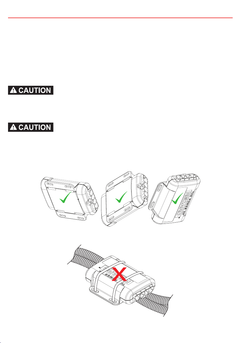
The Tow-Pro™Elite can be mounted in any orientation as long as the installation is
secure and the main unit cannot move or change orientation once installed. A change of
orientation will affect the system calibration.
Ensure that the Tow-Pro™Elite is mounted securely in a fixed location. Failure to mount
securely will result in inaccurate braking force measurements and incorrect braking of
the trailer.
Ensure that the Tow-Pro™Elite is installed inside the vehicle cabin and away from any
environmental conditions that may cause damage, including engine heat, submersion in
water, salt spray and humidity. Exposure to these conditions may cause damage to the
unit’s circuitry and may cause erratic trailer braking.
5
Any Secure Orientation OK
Do Not Mount to Cables / Wiring Looms

2 INSTALLATION
2.2 Wiring the brake controller
A Fuse or Circuit Breaker of appropriate rating must be installed to protect the vehicle
system. Please refer to the installation instructions on page 7 for specific instructions on
where to install the Fuse or Circuit Breaker and for appropriate Fuse or Circuit Breaker
rating. The Fuse or Circuit Breaker must be installed as close as possible to the battery.
Ensure that the cable used to install the Tow-Pro™Elite is of adequate gauge to supply
the required current to operate the trailer brakes. Incorrect wiring can result in overheated
wires and may cause injury to persons, damage to the Tow-Pro™Elite and/or damage to
property.
The Tow-Pro™Elite does not act as a trailer lights voltage converter. The Tow-Pro™Elite
is designed to operate the trailer brake lights under certain conditions. If the trailer brake
lights require a different voltage to the input from the vehicle, damage to the trailer brake
lights may result.
2.2.1 Red Wire (Vehicle Brake light) Connection
The requirements for a suitable connection of a brake controller trigger wire are quite
specific. This connection point must:
• Provide battery voltage output while the vehicle brakes are applied.
• Have 0 volts output while the vehicle brakes are not applied
• Accept battery voltage input when the brake controller manual over-ride is operated
and illuminate at least the trailer brake lights.
• Accept the battery voltage input as above without causing any damage, spurious
vehicle operation or erroneous fault indication.
A relay should not be installed to drive the red wire as this would prevent the override
feature from working and may introduce dangerous voltage spikes.
For many vehicles, the brake light terminal of the trailer lighting socket provides a suitable
connection, however this is not necessarily suitable for all vehicles. Unfortunately REDARC
cannot recommend where to make this connection on a specific vehicle’s OEM wiring. For
further information contact the vehicle manufacturer.
6

2 INSTALLATION
2.2.2 Wiring Diagrams
To 24V Vehicle
Brake Light trigger
(refer to section 2.2.1)
To 12V Trailer
Brakes
Blue
Red
25A Fuse or
30A Circuit Breaker
(CBK30-EB)
24V Vehicle
Start Battery
Ground
White
Black
-
Dash mount
controls for
Tow-pro.
24V
INPUT
1.25mm²
1.25mm²
3.0mm²
3.0mm²
The Input Power (Black) wire should be
connected directly to the positive terminal of
the start battery via a Fuse or Circuit Breaker
and not through an Ignition source.
To 12V Vehicle
Brake Light trigger
(refer to section 2.2.1)
To 12V Trailer
Brakes
Blue
Red
25A Fuse or
30A Circuit Breaker
(CBK30-EB)
12V Vehicle
Start Battery
Ground
White
Black
-
Dash mount
controls for
Tow-pro.
12V
INPUT
1.25mm²
1.25mm²
3.0mm²
3.0mm²
The Input Power (Black) wire should be
connected directly to the positive terminal of
the start battery via a Fuse or Circuit Breaker
and not through an Ignition source.
7

2 INSTALLATION
2.3 Mounting the Remote Head
The Tow-Pro™Elite remote head is designed to be mounted at a distance from the main
unit, allowing for a neat, convenient installation and not impeding on lower leg airbags or
driver leg room. The Tow-Pro™Elite remote head is designed to be mounted on or around
the vehicle dashboard and when installed correctly, complies with Australian Design Rule
(ADR) 21, which sets requirements for devices mounted on the dashboard. The Tow-Pro™
Elite remote head can be mounted directly to the dashboard, to the centre console or
through a spare knock-out switch panel and requires only two holes to be drilled as per
the below diagram.
Ensure the remote head push-button activates correctly when installed into surfaces with
a thickness greater than 3.0mm. Failure to activate correctly would result in not being
able to activate the override function or change modes.
8
Ø3.5mm
Ø10.0mm
(drill pilot
hole first
or use a
spade bit)
7.5mm
*2.0 - 3.0mm
Turn shaft fully
anti-clockwise
Apply knob with
‘0’ aligned with
the level marker
on the bezel.
Applying the Knob
Torque to 0.8Nm

2 INSTALLATION
2.4 Active Calibration
When the unit is first powered, Active Calibration must first become confident in
the vehicle direction of travel. Until this time the LED will flash Blue/Green.
Time Time
During Calibration: Once Calibrated:
Active Calibration constantly monitors the vehicle’s direction of travel and allows the
Tow-Pro™ Elite to ‘learn’ and continuously confirm its mounting orientation. This process
occurs whilst the vehicle is moving and the brake is applied and will occur with or without
a trailer connected.
When the Tow-Pro™ Elite is first installed it will begin learning its mounting orientation
through Active Calibration as soon as you start driving, at this point Proportional Mode is
selected but not yet fully operational.
Until the Tow-Pro™ Elite has determined its mounting orientation the unit will function as
if in User-Controlled mode, this is indicated by the LED glowing green with blue flashes.
As the Tow-Pro™ Elite becomes more confident of its direction of travel the length of the
Blue flash will increase, to the point that the LED is solid Blue which indicates it is now
operating completely in Proportional mode.
Under normal driving conditions the Tow-Pro™ Elite will learn its mounting orientation
within 20 brake applications. Note that the braking must be perceptible (applying the
brake while stopped will not assist calibration).
If power is disconnected (for example, if the vehicle battery is changed) calibration
memory will be lost and the unit will recalibrate itself using active calibration. This is
similar to a radio losing its clock or preset station memory.
If no trailer is connected, Active Calibration will occur as normal without any indication
from the LED. The LED will already be Blue when the trailer is connected. Essentially,
whether a trailer is connected or not, just drive normally and Active Calibration will ensure
the Tow-Pro™ Elite learns the correct direction of travel.
9
Otros manuales para Tow-Pro Elite
3
Este manual sirve para los siguientes modelos
1
Tabla de contenidos
Otros manuales de Controladores de Redarc

Redarc
Redarc Smart Start SBI12 Manual de usuario

Redarc
Redarc Tow-Pro EBRH-ACCNA Manual de usuario

Redarc
Redarc Solar SRPA0120 Manual de usuario

Redarc
Redarc SBI12-LLD Manual de usuario

Redarc
Redarc Tow-Pro Elite Manual de usuario

Redarc
Redarc SBI12-LLD Manual

Redarc
Redarc Tow-Pro Elite Manual de usuario

Redarc
Redarc Tow-Pro Elite Manual de usuario