RAK 4631 Manual de usuario

Documentation Center
RAK4631 Quick Start Guide
This guide introduces the RAK4631 WisBlock Core LPWAN Module and how to use it. RAK4631 consists of an
nRF52840 MCU and an SX1262 LoRa® chip making it ideal for various IoT projects.
Prerequisite
What Do You Need?
Before going through each and every step on using RAK4631 WisBlock Core, make sure to prepare the necessary
items listed below:
Hardware
RAK4631 WisBlock Core LPWAN Module
Your choice of WisBlock Base
Your choice of WisBlock Modules
USB Cable
Li-Ion/LiPo battery (optional)
Solar charger (optional)
RAK4631 is also included in various WisBlock kits in the RAKwireless store:
WisBlock Starter Kit - This includes a RAK4631 with RAK5005-O WisBlock Base board. This kit is ideal to get
started immediately with WisBlock.
WisBlock Kit - This is like the Starter Kit but with various WisBlock modules already included on the kit like
sensors, IO, and other interfaces.
WisBlock Connected Box - This is like the WisBlock Kit but cheaper because some modules and peripherals
are not included. Excluded parts are RAKBox-B5, RAK1921, RAKDAP1, electric screwdriver (manual is
included), and battery holder.
Helium Developer Kit - This is the WisBlock Kit for the Helium brand.
Software
You can choose Arduino IDE or Platform IO in coding the RAK4631 WisBlock Core.
Programming RAK4631 via Arduino IDE:
Download and install the Arduino IDE .
⚠
WARNING
If you are using Windows 10.
Do NOT install the Arduino IDE from the Microsoft App Store. Instead, install the original Arduino IDE from
the Arduino official website. The Arduino app from the Microsoft App Store has problems using third-party
Board Support Packages.
To add the WisBlock Core boards on your Arduino board, you need to install the RAKwireless Arduino BSP. You
can follow this complete guide on adding the BSP in Arduino IDE . You can also have a look at the
RAKwireless Arduino BSP GitHub repository .

Documentation Center
In Arduino IDE, once you installed the BSP, some examples for RAK4631 will be automatically included on the list
of examples when you select WisBlock Core RAK4631 Board in the Board Manager.
Programming RAK4631 via Platform IO:
Platform IO for RAK4631 complete setup guide
📝
NOTE
Updated and complete WisBlock examples can be found in the WisBlock Examples repository which
contains source codes that you can copy-paste and upload.
Aside from that, each WisBlock Modules has its own quick start guide to help you in your WisBlock
journey.
Product Configuration
Hardware Setup
RAK4631 to WisBlock Base
The RAK4631 will not work without a WisBlock Base board. The WisBlock Base provides a USB connection for
programming the RAK4631. It also provides a power source and various interfaces to RAK4631 so that it can be
connected to other WisBlock modules via different module slots.
RAKwireless offers many WisBlock Base Boards compatible with WisBlock Core. It is highly recommended for
you to look on these WisBlock Base boards to see what matches your requirements in terms of available module
slots, power supply options, and overall size.
To illustrate, RAK4631 can be connected to RAK5005-O WisBlock Base, as shown in Figure 1.
Figure 1: RAK4631 Connection to WisBlock Base RAK5005-O
There are few pins that are exposed on RAK5005-O, and you can easily use them via header pins. The labels are
at the back, as shown in Figure 2.

Documentation Center
Figure 2: WisBlock Base exposed pins
More information can be found on the official documentation of the specific WisBlock Base you used in your
project.
For RAK5005-O WisBlock Base with RAK4631 WisBlock Core, the accessible GPIO pins are defined as follows in
the Arduino IDE and Platform IO:
WB_IO1 for IO1 pin
WB_IO2 for IO2 pin (Also used to control the 3.3 V supply of some WisBlock Modules to achieve low-power
IoT devices.)
WB_A0 for AIN
There are usable LEDs as well that can be controlled by the RAK4631 on the WisBlock Base board:
LED_GREEN
LED_BLUE
UART1 and I2C_1 are also exposed on the header of the WisBlock Base board.
RAK4631 has a native USB peripheral onboard (Serial), which is used for programming and Serial debugging
and two usable hardware UART1 and UART2 (Serial 1 and Serial 2). UART1 is accessible to WisBlock Slot A,
WisBlock IO slot, and the exposed header pins. UART2 is accessible only on the WisBlock IO slot.
The I2C_1 header pins are as well shared to the WisBlock Base Slots A to D. The second I2C_2 is available
only on the WisBlock IO slot.
RAK4631 to WisBlock Modules
RAK4631 WisBlock Core is designed to be interfaced with other WisBlock Modules like sensors, displays, and
other interfaces. You need to connect these modules to the compatible slots on the WisBlock Base.
Each WisBlock Modules that will be used with RAK4631 WisBlock Core have a dedicated quick start guide you
can follow on how to connect to the WisBlock Base.
Listed are the quick start guide of some WisBlock modules you can buy from our store :
📝
NOTE
The listed links are just examples. All WisBlock Modules have their own quick start guide that you can
use as a reference to get started on specific modules.
RAK1901 Quick Start Guide
RAK1902 Quick Start Guide
RAK1903 Quick Start Guide
Figure 3 shows an illustration on how you can combine various WisBlock Modules with the RAK4631 WisBlock
Core via the WisBlock Base board.

Documentation Center
Figure 3: RAK4631 Connection to WisBlock Base and other WisBlock Modules
Assembling and Disassembling of WisBlock Modules
Assembling
Figure 4 shows how to mount the RAK4631 module on top of a WisBlock Base board (RAK5005-O). Follow
carefully the procedure defined in WisBlock module assembly/disassembly instructions in order to secure the
connection safely. Once attached, carefully fix the module with one or more pieces of M1.2 x 3 mm screws
depending on the module.
Figure 4: RAK4631 Mounting Sketch
Disassembling
The procedure in disassembling any type of WisBlock modules is the same.
1. First, remove the screws.
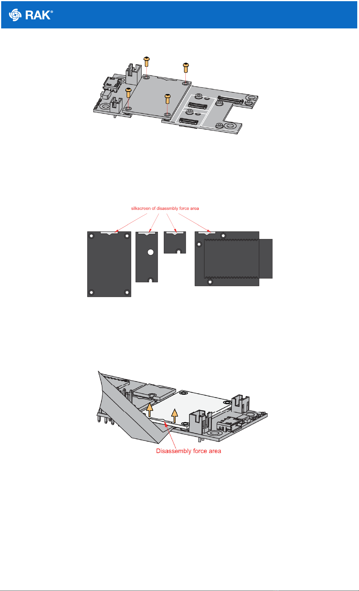
Documentation Center
Figure 5: Removing screws from the WisBlock module
2. Once the screws are removed, check the silkscreen of the module to find the correct location where force can
be applied.
Figure 6: Detaching silkscreen on the WisBlock module
3. Apply force to the module at the position of the connector, as shown in Figure 7, to detach the module from the
baseboard.
Figure 7: Applying even forces on the proper location of a WisBlock module
LoRa and BLE Antenna
Another important part component of RAK4631 is the antennas.

Documentation Center
Figure 8: LoRa Antenna
Figure 9: BLE Antenna
You need to ensure that the antenna is properly connected to have a good LoRa signal. Do not power the module
without an antenna connected to the IPEX connector to avoid damage to the RF section of the chip.
RAK4631 has a label on its sticker where to connect the antennas, as shown in Figure 10.
Figure 10: RAK4631 Antenna Label
📝
NOTE
Detailed information about the RAK4631 BLE and LoRa antenna can be found on the antenna datasheet
.
⚠
WARNING
When using the LoRa or Bluetooth Low Energy transceivers, make sure that an antenna is always
connected. Using these transceivers without an antenna can damage the system. Make sure to fix the
module with the screws to ensure a proper function.
Battery and Solar Connection

Documentation Center
RAK4631 can be powered via the USB cable or Li-Ion/LiPo battery via the dedicated connectors, as shown in
Figure 11. The matching connector for the battery wires is an JST PHR-2 2 mm pitch female .
This illustration uses RAK5005-O as WisBlock Base. There are other WisBlock Base boards available and you
need to check the datasheet of the specific WisBlock Base board for the right polarity and other parameters.
⚠
WARNING
Batteries can cause harm if not handled properly.
Only 3.7-4.2 V Rechargeable LiPo batteries are supported. It is highly recommended not to use other
types of batteries with the system unless you know what you are doing.
If a non-rechargeable battery is used, it has to be unplugged first before connecting the USB cable to
the USB port of the board to configure the device. Not doing so might damage the battery or cause a
fire.
Only 5 V solar panels are supported. Do not use 12 V solar panels. It will destroy the charging unit and
eventually other electronic parts.
Make sure the battery wires match the polarity on the WisBlock Base board. Not all batteries have the
same wiring.
Figure 11: WisBlock Base Connection
Figure 12: Battery Connection
The battery can be recharged as well via small solar panel, as shown in Figure 13. The matching connector for
the solar panel wires is an JST ZHR-2 1.5 mm pitch female .

Documentation Center
Figure 13: Solar Panel Connection
Specification of the battery and solar panel can be found on the datasheet of the WisBlock Base.
Software Setup
RAK4631 WisBlock Core is designed to be interfaced with other WisBlock Modules like sensors, displays, and
other interfaces. To make useful devices, you need to upload a source code to the RAK4631. Before you continue,
you should have either the Arduino BSP or Platform IO already setup.
RAK4631 Example Repository
To quickly build your IoT device with less friction, example codes for RAK4631 to be used on all WisBlock Modules
are provided.
You can access the codes on the WisBlock Example code repository . The example codes compatible only with
RAK4631 are in the folders RAK4631 . The shared examples of the WisBlock Core are in the common folder.
To use these examples, you have two options: Arduino IDE or Platform IO.
RAK4631 on Arduino IDE
Some example codes of various WisBlock Modules like the RAK1901 and RAK1902 are available in the Arduino
IDE once you install the BSP for the Arduino IDE, as shown in Figure 14. The updated and complete WisBlock
examples are still in the WisBlock Examples .

Documentation Center
Figure 14: RAK4631 WisBlock Core Examples
It is highly recommended to also check the dedicated quick start guide that you can follow on various WisBlock
Modules. Each quick start guide of these modules contains the detailed steps on how to open the example codes
and upload them to the RAK4631.
Listed are the examples where you can check the Software Setup on the quick start guide of the following
WisBlock Modules:
📝
NOTE
The listed links are just examples. All WisBlock Modules have their own quick start guide that you can
use as a reference to get started on specific modules.
RAK1901 Quick Start Guide
RAK1902 Quick Start Guide
RAK1903 Quick Start Guide
RAK4631 on Platform IO
For the Platform IO, get the example codes on the WisBlock Example code repository and add the necessary
libraries individually. Then you can compile the example code.
Connecting RAK4631 to LoRaWAN
RAK4631 is the WisBlock Core capable of LoRaWAN connectivity.
There is an example on how to start with LoRaWAN in the RAK WisBlock examples in Arduino IDE named
LoRaWAN_OTAA_ABP . This is also available in the WisBlock Repository .

Documentation Center
Figure 15: RAK4631 LoRaWAN Example
Configuration of LoRaWAN Example Code
There are configurations that you need to set up to ensure that the device can join a LoRaWAN Network server.
The guide below will explain the default settings and how to configure them.
1. Setup the region.
Default is EU868.
You can change this to a region that is applicable to you like LORAMAC_REGION_US915 , LORAMAC_REGION_AU915 ,
etc.
2. Setup the activation method.
Default is OTAA.
To configure the device to ABP, you need to make this boolean variable false .
3. Setup the message type if confirmed or not.
Default is confirmed message.
You can change to unconfirmed message by changing the value to LMH_UNCONFIRMED_MSG .
4. Setup device class.
Default is Class A.
LoRaMacRegion_t g_CurrentRegion = LORAMAC_REGION_EU868;
bool doOTAA = true;
lmh_confirm g_CurrentConfirm = LMH_CONFIRMED_MSG;
Tabla de contenidos
Otros manuales de GPS de RAK


