
Radium EMS Manual de usuario

INSTRUCTION MANUAL
PLUG AND PLAY EMS KIT
LOTUS ELISE/EXIGE/2-ELEVEN
2004+ with 2ZZ-GE ENGINE
DOCUMENT 19-0046
Radium Engineering LLC
©2012, All right reserved

Table of Contents
1. Introduction
2. Warnings and Cautions
3. Before Getting Started
4. 2004-2005 EMS Mounting
5. 2006+ EMS Mounting
6. Installation of Accessories
7. Before Initial Start-Up
8. Engine Tuning
9. Tables and Pinouts

1. INTRODUCTION
The Radium Engineering Plug and Play Engine Management System (EMS) gives the user complete
control over all engine parameters and also adds extra functionality for modified vehicles. The Radium
EMS itself is a highly modified AEM EMS-4. The stock ECU is retained to run the CAN-BUS dashboard,
electronic throttle (when equipped) and other secondary tasks. The EMS gives the user full control over
fueling, ignition timing and VVTi-L (cam position and lift). It also offers added features such as electronic
boost control, wideband O2 feedback, traction control, data logging, and much more.
To get familiar with the AEM EMS-4, reference the CD included in the kit. Download the AEMTuner
software and user manual. Note: visit www.aempower.com to get all of their latest updates. Read all
accompanying literature and become familiar with the operation of an AEM EMS-4 and how it functions.
Install the AEMTuner software on a laptop that can be used for initial start-up checks. The EMS is
shipped from Radium without a start-up calibration loaded. The engine will NOT start without a
loaded calibration file. Calibrations can be downloaded from www.radiumauto.com. The calibration
supplied by Radium is not a final tune. The vehicle must still be evaluated by a professional tuner
familiar with AEM software and tuning.
2. WARNINGS AND CAUTIONS
Use this system with EXTREME caution! The EMS System allows for total flexibility in engine tuning,
however misuse of this product can lead to major engine/vehicle damage. If you are not well versed
in engine dynamics and the tuning of management systems or are not PC literate, please do not
attempt installation or tuning of this product. For technical assistance, please visit the AEM Electronics
Forum or visit a local qualified AEM tuner near you. Radium and AEM hold no responsibility for any
engine damage that results from the misuse of this product! Failure to follow proper precautions may
result in engine damage or other collateral damage. Radium will not be held responsible for any
damage resulting from poor tuning or improper installation.
-Before driving the car, the calibration must be checked by a professional. Pre-loaded calibrations are
only a starting point for tuning and should not be considered fully safe.
-All inputs and outputs should be verified before starting the vehicle. This is done by connecting a
laptop computer and communicating with the EMS. Engine parameters can be observed and verified.
-All preliminary tuning should be done with high-octane fuel as an added safety factor to resist
accidental detonation from tuning.
-This EMS system is NOT EMISSIONS COMPLIANT and as a result is legal for off-highway use only.
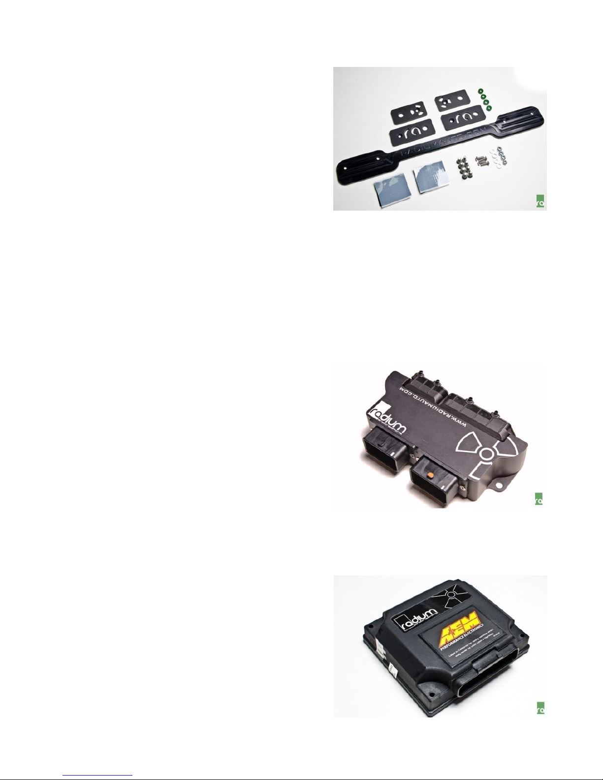
3. BEFORE GETTING STARTED
For installations that are using a Radium Turbocharger
kit, the rear clamshell should ideally be removed to gain
easy access for installation (running wires, vacuum lines,
etc). Radium sells clamshell kits that help make this
process easier. For installations in naturally aspirated or
factory supercharged vehicles, clam shell removal is not
necessary but will help speed the installation.
Alternatively, for naturally aspirated vehicles, simply
removing the deck lid (or hatch) will allow access to the
critical areas for the plug and play installation.
Familiarize yourself with the location of engine control related components. If installing gauges, a
mounting location must be determined. Access to the area behind the LH seat is required for the EMS
installation. Removal of the speaker panel is necessary.
The following components are included in the basic Radium Lotus EMS kit:
JUMPER BOX
All Lotus EMS kits use a Radium jumper box (shown on
right). The jumper box consists of a conformal coated
printed circuit board and a billet aluminum enclosure.
The factory Lotus ECU connectors plug into this unit
making the kit plug and play. The included main harness
plugs into the other side of the jumper box. This unit
always mounts in the engine bay. However, depending
on the model year of the Lotus, this jumper box may
mount as such or 180 degrees rotated. The jumper box’s
connector header that matches the engine harness’
connectors will always face downwards.
RADIUM/AEM EMS-4
The circuitry of the AEM EMS-4 included in the kit has
been modified by Radium Engineering to make it
compatible with the Lotus electronics. Do not replace the
Radium EMS with a standard off-the-shelf AEM EMS-4
that does not have a Radium sticker. Contact Radium
Engineering should a replacement be needed.
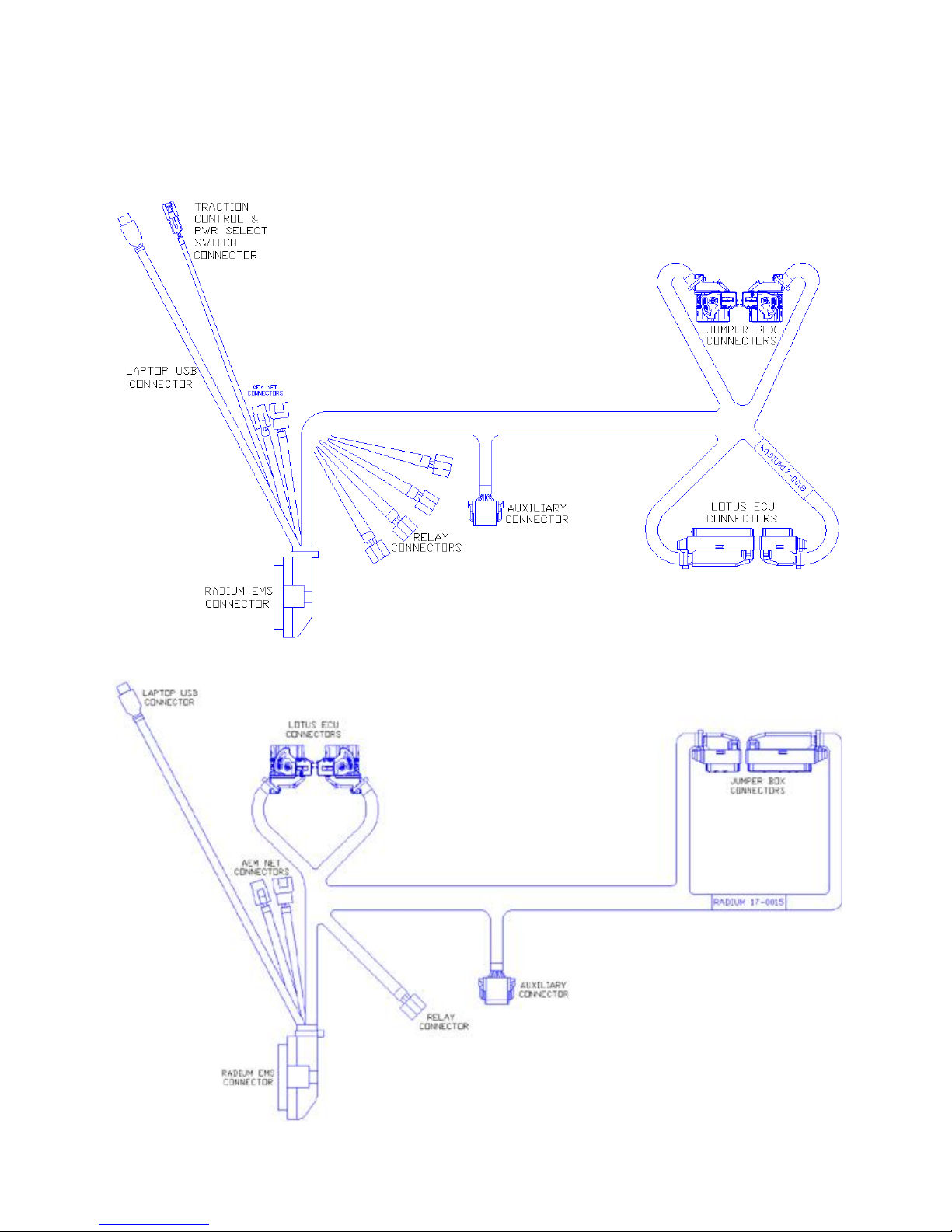
MAIN WIRING HARNESS
The model specific main wiring harness is included and links the jumper box to all other components in
the system including the Radium EMS. This harness is custom engineered for the Lotus application by
Radium Engineering and makes installation plug and play.
Radium Main Harness, 2004-2005 Lotus
Radium Main Harness, 2006-up Lotus

LOTUS ECU CONNECTORS
The ECU connectors used on the 2004-2005 Lotus models are different than the 2006+ ECU connectors.
Understanding how both of these connectors work will make installation easier. Experiment with these
connectors and the Radium jumper box to see how they work before the system is installed in the car.
Familiarity with both connector styles is required for all installations.
The 2006+ connectors use a rotating latch to
lock the connector to the header. Shown at
left is a connector in its fully unlocked state
ready to be inserted into the header.
After insertion, rotate the latch and it will
draw the connector into the header. Once
fully engaged, the latch will lock in place.
To release, push the small release button with
your thumb (shown) and rotate the latch back
to the unlocked position.
The 2004-05 connectors use "slide locks" to
engage the connectors with the headers. The
picture shown depicts the slide in the fully
unlocked state. The slide has a tab that can
be pulled to release the latch mechanism.
The slide must be fully open, as shown, in
order for the connector to be inserted into
the header. Once inserted, push the slide
closed to fully engage the connector to the
header connector.

4. 2004-2005 EMS SYSTEM MOUNTING
Follow the instructions below if installing the Radium Plug and Play EMS kit on a 2004-2005 Lotus with a
cable actuated throttle body.
1. Disconnect battery negative cable.
2. Locate the factory engine control unit (ECU) on the firewall, near the engine intake manifold.
3. Unplug both the connectors going into the ECU. This is done
by pulling the connector slide lock mechanism, as shown.
4. Situate the Radium main wiring harness in the engine bay and
plug the connectors that match the factory connectors (from
previous step) into the factory ECU. Make sure the slide locks are
in the unlocked position as the connector is inserted into the ECU
header. Once inserted and seated, slide the lock closed and the
connector will fully engage into the header. Do this for both
connectors.

6. Plug the factory ECU connectors into the Radium jumper box’s lower
ECU header. Make sure the slide locks are in the unlocked position as the
connector is inserted into the header. Once inserted and seated, slide the
lock closed and the connector will fully engage into the ECU header. Do
this for both connectors.
5. Use a 10mm socket to remove the LH side nut holding the ECU to its
mounting bracket, leave the washer in place. Using a 13mm socket,
remove the other mounting nut on the bottom RH side of the ECU. Leave
ECU in place and do not remove from firewall. In the EMS kit, locate the
two hex standoffs. Thread these onto the aforementioned studs. They
have different thread pitches to correspond with the threaded studs
(green = M8x1.25, black = M6x1.0). Tighten with a ½” wrench or socket.

7. Use the included M6x1x12mm Allen screw with M6 washer and the
M8x1.25x16mm hex screw with M8 washer to mount the Radium jumper
box to the hex standoffs from step 5.
8. On the Radium main harness, locate the two ECU connectors similar to
what is shown in the picture. Plug these into the top two headers of the
Radium jumper box. The plugs are keyed to work in the correct headers and
are color coded black and brown. Be careful not to use the incorrect header
socket. Once the plug is inserted, rotate the latch which will fully seat the
connector and lock it in place.

9. Engine side of the main harness installed.
10. Remove the air intake system and drill out the six rivets holding the air box
bracket to the bulkhead wall. Four rivets are located on the vertical face (shown) and
two are located on the top face hidden by the carpet. Insert the included M5 button
head Allen screws into the holes as place holders until the EMS bracket is installed
inside at a later step.
Tabla de contenidos


