QView QD1200 Manual de usuario

PRECAUTIONS
Please follow these precautions:
To prevent fire or shock hazard, do not expose the unit to rain or moisture.
To prevent electrical shock, do not open the cabinet. Refer to qualified
personnel for service only.
Do not use the unit continuously for more than 24 hours with camera auto
focus on. It may cause damage to the camera lens.
Be careful not to spill water or other liquids onto the unit, or allow combustible
or metallic objects to get inside the cabinet.
Unplug the visualizer from the wall outlet when it is not being used for
a long period of time.
Clean the cabinet with a soft cloth lightly moistened with a mild detergent
solution.
Clean the lens carefully with an air spray or soft dry cloth to avoid scratching
it.
When the lamps flash or become dark, they should be replaced with new
ones.
Avoid switching arm lights and back light frequently.
CONTACTS:
QOMO Hitevision, LLC
Toll Free: 1-866-990QOMO
Web: www.qomo.com
1

CONTENTS:
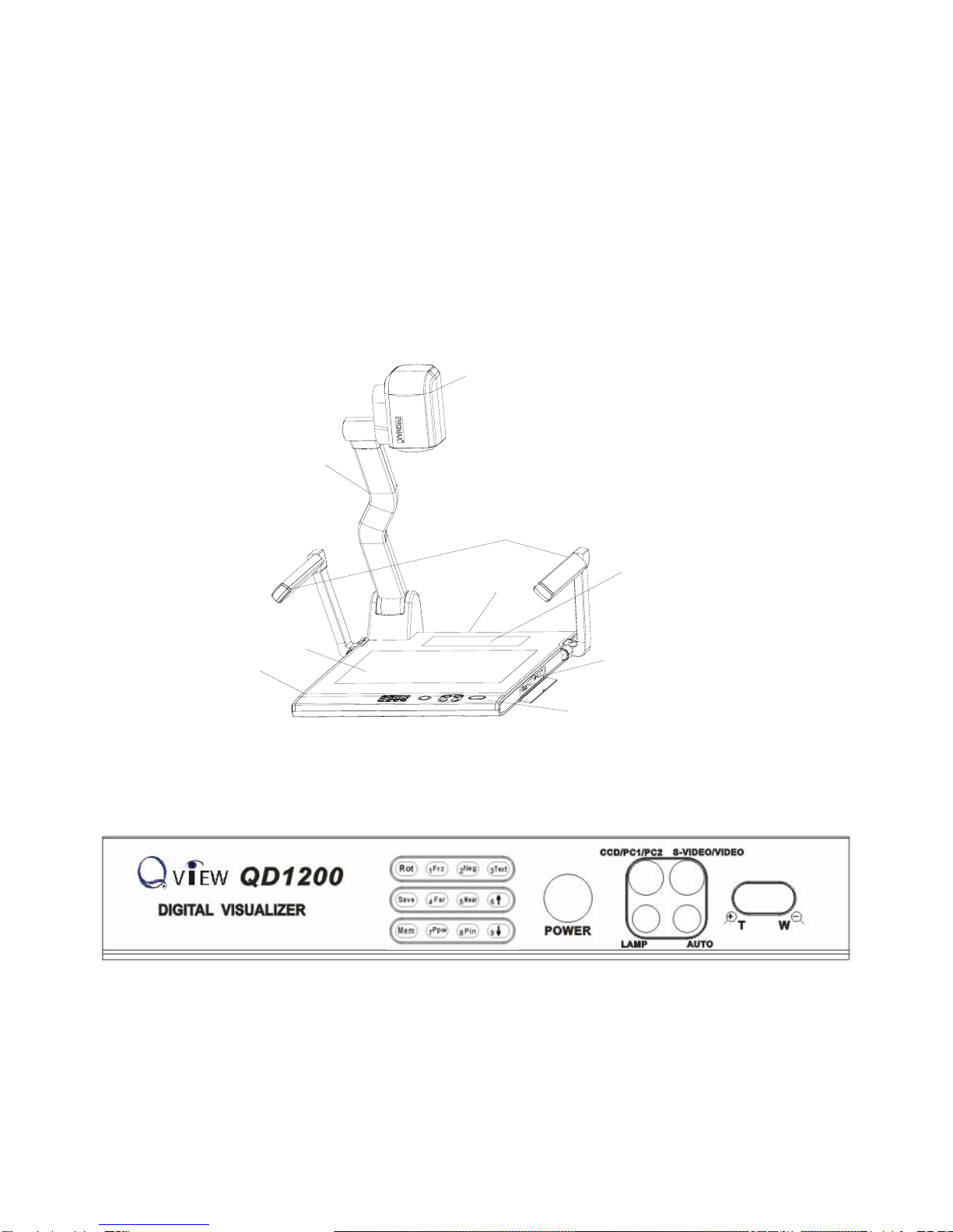
PARTS IDENTIFICATION............................................................................... 3
CONTROL PANEL.......................................................................................... 3
BUTTON INSTRUCTION................................................................................ 4
REMOTE CONTROL...................................................................................... 5
CONNECTIONS ............................................................................................. 6
BASIC PREPARATIONS................................................................................. 6
OUTPUT MODE AND VERTICAL FREQUENCY (60Hz).............................. 10
PAL/NTSC VIDEO OUTPUTS ...................................................................... 10
INSTALLING QOMO VISUALIZER SOFTWARE...........................................11
WORKING ON THE STAGE......................................................................... 13
WORKING OUTSIDE THE STAGE............................................................... 13
LIGHT ........................................................................................................... 14
ADJUSTING IMAGE SIZE............................................................................ 14
WORKING WITH NEGATIVES..................................................................... 14
FOCUSING................................................................................................... 15
FREEZING IMAGE ....................................................................................... 15
BRIGHTNESS ADJUSTMENT...................................................................... 15
WHITE BALANCE ADJUSTMENT................................................................ 15
AUTO ADJUSTMENT................................................................................... 15
TEXT/IMAGE MODE..................................................................................... 15
COLOR AND B&W MODE SWITCH............................................................. 16
SWITCHABLE VIDEO INPUTS .................................................................... 16
SWITCHABLE RGB INPUTS........................................................................ 16
PROJECTOR ON/STANDBY........................................................................ 16
PROJECTOR INPUTS SELECTION............................................................. 16
IMAGE ROTATION ....................................................................................... 16
IMAGE REVERSION .................................................................................... 17
INFRARED REMOTE CONTROL................................................................. 17
PRESET FUNCTION.................................................................................... 17
3 X 3 MULTIPLE SCREEN DISPLAY............................................................ 17
USB PORT.................................................................................................... 17
2

USB IMAGE CAPTURE................................................................................ 18
CONTROLLING THE VISUALIZER FROM THE COMPUTER..................... 19
CONTROLLING PROJECTOR BY VISUALIZER.......................................... 19
FOLDING THE UNIT..................................................................................... 23
SPECIFICATIONS ........................................................................................ 24
TECHNICAL SUPPORT................................................................................ 26
PARTS IDENTIFICATION
Arm lights
Camera
Camera stand
Back light
Remote control slot
Operation panel
Stage
Connectors
Connectors
Button instruction
CONTROL PANEL
Rot (Rotate the image)
Frz (Freeze the image)
Neg (Display film negatives)
Text (Switch between image/text mode)
3

Save (Save captured images)
Far/Near (Focus far or near)
Mem (Multiple Screen Display)
Ppw (Control the projector On/Standby)
Pin (Projector input signal selection)
/(Move the image up/down)
POWER (Control the visualizer On/Off)
CCD/PC1/PC2 (CCD/RGB input signal selection)
S-VIDEO/ VIDEO (S-VIDEO/ VIDEO input signal selection)
LAMP (Control the arm lights and back light)
AUTO (To auto adjust brightness, auto white balance and auto focus)
+
T/
W
(Increase and decrease magnification)
BUTTON INSTRUCTION
4

REMOTE CONTROL
POWER (Control the visualizer power On/Off)
ROTATE (Rotate the image)
FREEZE (Freeze the image)
LAMP (Control the arm lights and back light)
SAVE (Save captured images)
NEG (Display film negatives)
MIRROR (V-reverse the image)
XGA (Switch between SVGA mode and XGA mode)
RECALL (Multiple screen display)
TEXT (Switch between image/text mode)
B&W (Switch between Color mode and Black & White mode)
SPLIT (Image split function)
PROJECTOR POWER (Control the projector On/Standby)
PROJECTOR INPUT (Projector input signal selection)
EXIT (Exit selected function)
TELE/ IDE (Increase and decrease magnification)
W
FAR/NEAR (Focus near or far)
5

AUTO (To auto adjust brightness, auto white balance and auto focus)
CCD/PC1/PC2 (CCD/RGB input signal selection)
S-VIDEO/ VIDEO (S-VIDEO/ VIDEO input signal selection)
VOLUME+/- (Increase or decrease the volume)
RED+/- (Increase or decrease the red hue)
BLUE+/- (Increase or decrease the blue hue)
BRIGHT+/- (Increase or decrease the brightness)
SCROLL /(Move the image up/down)
CONNECTIONS
#1 AUDIO OUT #2 VIDEO OUT #3 S-VIDEO OUT
#4 VIDEO AUDIO IN #5 VIDEO IN #6 S-VIDEO AUDIO IN
#7 S-VIDEO IN #8 PC AUDIO IN
#9 PROJECTOR Connector #10 COMPUTER OUT
USB
PROJECTOR MIC
VIDEO
OUT
AUDIO AUDIO
OUT
S-VIDEO
IN
VIDEO
RGB IN AUDIO IN RS232
Side Panel
#11 COMPUTER IN #12 POWER OUT/IN
#13 PROJECTOR RS232 Connector #14 MIC IN
#15 USB Connector #16 RGB IN
#17 RGB AUDIO IN #18 COMPUTER RS-232 Connector
BASIC PREPARATIONS
8
PROJECTOR OUT -COMPUTER- IN OUT-12V- IN
AUDIO IN
S-VIDEO
7
IN
AUDIO
18
6

1. Use one hand holds the base of the visualizer, use the other hand
carefully lift up the camera stand of the unit.
2. Open the arm lights and rotate the camera head until they are in proper
positions.
Arm lights
3. Making connections:
Before making any connection, turn off all the power, including power of
the visualizer and the equipment to be connected.
Step 1: Connect power source.
First connect the power cord to the 12V IN connector.
Step 2: Connect to the projector.
7

Connect visualizer’s PROJECTOR port to the RGB IN port of the projector
port with the RGB cable provided together the visualizer.
Projector
RGB Input
Screen
RS232 Cable
Side Panel
MIC
PROJECTOR USB RGB IN AUDIO IN RS232
PROJECTOR
Rear Panel
S-VIDEO
OUT
AUDIO VIDEO
OUT
AUDIO
AUDIO VIDEO
IN
S-VIDEO
IN
AUDIO IN OUT -COMPUTER- IN OUT-12V- IN
If you need control a projector with the visualizer, please use the projector
RS232 cable (6-pin to 9-pin) to make the connection between the projector
and the visualizer. Some projector models may require a converter cable in
addition to this standard RS232 cable to connect to the projector control
port, for the pin locations and shape of some projectors’ control port
connector may be different from the connector of a standard RS232 cable.
After the visualizer is connected to the projector, you can control projector’s
power on, standby and input selection with the visualizer. (For projectors
other than Hitachi, the Code Writing program that comes with the visualizer
is required for this function.)
Step 3: Connect to a desktop computer.
RS232
Cable
MIC
PROJECTOR
Computer
USB RGB IN AUDIO IN
8RS232
Side Panel
RGB Output
To the
Monitor
USB Connector
AUDIO IN
OUT
AUDIO VIDEO
OUT
VIDEOAUDIOS-VIDEO
IN
S-VIDEO
AUDIO
IN
PROJECTOR OUT -COMPUTER- IN OUT-12V- IN
Rear Panel

Note: You can connect a laptop computer to the RGB IN port of side panel
with a RGB cable.
Step 4: Connect to the first video equipment with S-Video input.
Output of the S-Video signal from the visualizer to the projector is already
done in the step 2, where the RGB cable comes out from the visualizer and
goes to the projector. After the connections as steps 2, 3, 4 are made, input
signals from the computer、visualizer CCD and S-Video are going to the
RGB1 input on the projector and will be displayed on the projector screen
as RGB1. These signals can be seen in turn when pressing
“CCD/PC1/PC2” and “S-VIDEO/VIDEO” on the control panel of the
visualizer.
AUDIO
IN
S-VIDEO
OUTOUT
VIDEO AUDIO VIDEO
Video equipment
S-Video out
Audio out
Audio input
(or amplifier/speaker equipment)
Projector
S-Video Cable
S-VIDEO
AUDIO
IN
PROJECTOR
Rear Panel
AUDIO IN OUT-12V- IN
OUT -COMPUTER- IN
Step 5: Connect to the second video equipment with video input.
9
Video in
Projector Color monitor
S-VIDEO
AUDIO
OUTOUT
AUDIO VIDEO S-VIDEO VIDEO
IN IN
AUDIO
Rear Panel
AUDIO IN PROJECTOR OUT -COMPUTER- IN OUT-12V- IN
Video equipment
Audio out
Video Cable
Video out

Step 6: Connections for external control from the computer.
Use the computer RS232 cable (9-pin to 9-pin) to make the
RS 232 connector
USB connector
of the computer
of the computer
USB cable RS-232 cable
Side Panel
USB
PROJECTOR MIC RGB IN AUDIO IN RS232
connections shown below to control the visualizer from an external
computer.
USB connection enables capturing still images / video streams from
the visualizer to the computer. Special software is required for this
operation.
4. Turn on the power by pressing the “POWER” button.
OUTPUT MODE AND VERTICAL FREQUENCY (60Hz)
The RGB output can output a signal in the SVGA /XGA format.
In order to achieve the best picture quality you must set the outputs of the
Visualizer to match the native resolution of your display unit.
PAL/NTSC VIDEO OUTPUTS
The S-Video and composite video outputs are set to NTSC (PAL) during
manufacturing.
10
Otros manuales para QD1200
1
Tabla de contenidos
Otros manuales de Presentador digital de QView
Manuales populares de Presentador digital de otras marcas

Samsung
Samsung SDP-850 Manual de usuario

Dukane
Dukane DV-P303A Manual de usuario

RemotePoint
RemotePoint Presenter Global Manual de usuario

Kensington
Kensington Wireless Presenter with Laser Pointer Instrucciones de funcionamiento

NEC
NEC DS1-MP10RX2 Manual de funcionamiento

Logitech
Logitech R800 - Professional Presenter Presentation Remote... Manual de usuario


