QuickTec QuickTherm HF Manual de usuario

QuickTherm HF Room Thermostat
QuickTherm HF Room Thermostat Smart
Operating and installation instructions
GB

02
For the Installer / Installation manual
1. Use
The Universal Temperature Controller QuickTherm HF Room Thermostat Smart combines controllers for 3 different applications.The following applications
can be selected:
•Room Temperature Controller •Room Temperature Controller with Limiter •Floor Heating Controller
2. Select application
•Press OK
•Press OK
•Select Application (ROOM, LIMITER, FLOOR)| FLOOR is factory pre-set
•Press OK
Note:
In case of changing the application, the user- and Installer-settings will be set to it‘s default values.
Select H1 = Application
3. Manual
Depending on selected application the suitable manual has to be used:
•ROOM
→
from page 3
•FLOOR
→
from page 19
•LIMITER
→
from page 35
CODE = 7
Select Installer settings
•Press key MENU then move forward with key +
•At “Installer settings” press OK

03
User and installation guide Room Temperature Controller
1. Principle of operation
The programmable room temperature controller QuickTherm HF RoomThermostat Smart allows programming switching events (up to 9) and temperatures
according to personal needs.After installation the device automatically shows the time of day and the room temperature. In AUTO mode, the Heater
(Cooler) will be automatically activated
according to programmed time and temperature. Program 1 is the default pre-set program (see 8.).The room temperature will be controlled according to
the temperature measured by the internal or remote sensor.The Heater will be switched on when the temperature drops below the current set-point.
Actual Day
Actual Room Temperature
Calling for Heat (Blinks if detached from power module or there is no mains power)
Helping text
Mode = AUTO
Time = 14:31
2. Installation
Caution!
This device must be installed by a qualified electrician, according to the wiring diagram on the device and in compliance with all applica-
ble safety regulations.
Appropriate installation measures must be taken to achieve the requirements of protection class II.
This device, is used to control the temperature only in dry rooms, under normal environmental conditions.This electronic device conforms
to EN 60730, It is an “independently mounted control” and works according to operating principle 1C.

04
4. Features
•One line text display for simplified operation
•Back light
•Real time clock (setting of year, month, day, time)
•Automatic Summer- Winter time change over
•Max 9 events per day (each day independently)
•Pre-set and adjustable programs
•Optimum-Start
•Arm chair programming (with display unit removed)
•OFF-Function, Key to be pressed for 10 sec
•Holiday-Mode (date from – until can be set)
•Timer (Party) specific temperature for configurable duration
•Energy consumption display (heating on time * cost)
for last 2 days, -week, -month, -year
•Energy cost per hour configurable
•Frost protection
•Range limits for adjusting max and min temperature
•Access protection
•Operating language can be selected
•Control mode PWM or ON/OFF
•Minimum output on/off time and hysteresis configurable for
ON/OFF control
•Valve protection
•Heating or Cooling can be selected.
•Adaptation to valves normally open or normally closed
•Measures the room temperature with the internal sensor or a
remote sensor
3. Use
The electronic Room Temperature Controller QuickTherm HF Room Thermostat Smart can be used to control the room temperature in
conjunction with:
•Thermal actuators for e.g. water based floor heating or convector heaters •Heatpumps
•Oil or Gas heaters •
Electric convector heaters, ceiling and storage heating
•Circulation pumps •
Cooling equipment
5. Mounting
The controller should be mounted at a location in the room which:
•can be easily accessed
•is free of curtains, cabinets, shelves, etc.
•allows free air circulation
•is not exposed to direct sunlight
•
is not draughty (when doors or windows are opened)
•is not directly influenced by the source of heat/cooling
•is not located on an outer wall
•is approx. 1.5 m above the floor
05
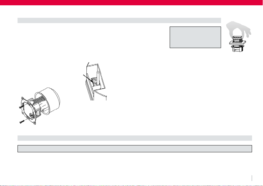
in a conduit box Ø 60 mm
•remove the display unit
•remove the frame
•Mount it following the reverse procedure
Fitting
Caution!
Mounting in plastic wall
boxes only
To insert or remove a flexible wire
press pin.
The plastic tab must be in place to pro-
vide insulation between the terminals/
wires and the mounting screw.
Connecting according to Wiring Diagram
For flexible or solid wires 1 - 2,5 mm2
Electric connection
Caution: disconnect electric circuit from supply

06
In order to measure the room temperature, instead of the internal sensor an external one can be used.
Remote or internal sensor selection can be made via menu item H1.
Lay sensor inside a protective tube (simplifies replacement). The sensor lead can be extended up to 50 m by using a cable and connections
suitable for 230 V. Avoid laying sensor cable alongside power cables, for example inside a conduit.
Connecting the remote sensor
Caution!
The sensor is at mains voltage.
6. Technical Data
Order Type QuickTherm HF Room Thermostat Smart
Supply voltage 230 V AC 50 HZ (195…253 V)
Temperature setting range 5 °C ... 30 °C; in 0,5 °C steps
Temperature resolution 0,1 °C steps
Output Relay NO contact
Switching current 10mA ... 10 (4) A, 230 V~
Output signal
PWM (Pulse Width modulation) or ON/OFF
PWM cycle time adjustable
Hysteresis adjustable (ON/OFF only)
Minimum programmable time 10 Min
Power consumption ~ 1,2 W
Accuracy of clock < 4 min / year
Power reserve ~ 10 years

07
Remote sensor (optional) Length 4 m,
can be extended up to 50 m.
Ambient temperature operating 0°C ... 40°C (without condensation)
Ambient temperature storage -20 °C ... 70 °C (without condensation)
Rated impulse voltage 4 kV
Ball pressure test 75 ± 2 °C
Voltage and Current for the purposes of
Interference measurements 230 V, 0,1 A
Degree of protection IP 30
Protection class of housing II (see Caution)
Pollution degree A
Software class 2
Weight ~ 100g
Energy class (acc. EU 811/2013,
812/2013, 813/2013, 814/2013) IV = 2 %

08
Caution!
Maximum length
of removed cable
insulation 8 mm.
Remote sensor
7. Wiring Diagram / Dimensions
Ø 7,8

09
8. Pre-set programs
There are 3 pre-set time/temperature programs in the controller. Pre-set program 1 (as shown below) is the default.Therefore, if pre-set
program 1 is the best program to suit the application, there will be no need to change the time/temperature settings on the device.
To select another program see 9. G1.
Programm 1
Events 1 2 3 4 5 6
Time 6:00 8:30 12:00 14:00 17:00 22:00
Temperature °C 21,0 18,0 21,0 18,0 21,0 15,0
Events 1 2 3 4 5 6
Time 7:00 10:00 12:00 14:00 17:00 23:00 / 22:00*
Temperature °C 21,0 18,0 21,0 21,0 21,0 15,0
Monday to Friday
Saturday and Sunday
*23:00 / 22:00
= 23:00 for Saturday

10
Programm 2
Events 1 2 3 4 5 6
Time 6:00 8:30 12:00 14:00 17:00 22:00
Temperature °C 21,0 18,0 21,0 18,0 21,0 15,0
Events 1 2
Time 7:00 23:00 / 22:00*
Temperature °C 21,0 15,0
Monday to Friday
Saturday and Sunday
*23:00 / 22:00
= 23:00 for Saturday
Tabla de contenidos
Manuales populares de Termostato de otras marcas

EWELLY
EWELLY EW-181 Manual de usuario

Prolon
Prolon T1100 Instrucciones de instalación

Computherm
Computherm Q20 Manual de usuario

Heatmiser
Heatmiser neoStat Manual de usuario

Aube Technologies
Aube Technologies TH111GFCI-NP 240 VCA Manual de usuario

Mars
Mars HEAT CONTROLLER IR Wireless Thermostat Manual de usuario


