Quadratec Q Series Guía de configuración

Q-Performance Stealth
Series Winch
with Integrated Solenoid
& Steel Winch Cable
Assembly and Installation Manual
#92122.4030 & #92122.4040
REQUIRED TOOLS:
Safety Glasses
Safety Gloves
Torque Wrench
13 MM Wrench
15 MM Socket
16 MM Wrench
2.5 MM Hex (Allen®) Key
4 MM Hex (Allen®) Key
#1 Phillips Head Screwdriver
READ ALL SAFETY MESSAGES AND UNDERSTAND ALL
INSTRUCTIONS AND PROCEDURE NOTICES
BEFORE ATTEMPTING TO INSTALL OR USE THIS PRODUCT.
US PATENT PENDING

2
Unpacking:
When unpacking, check to make sure all parts are included. If any part is missing or
broken, please call Quadratec Customer Service at 800-745-6037 as soon as possible.
Winch Assembly
Clutch
Handle
Winch Power Button
Hawse Fairlead
Fairlead
Hardware
Winch
Mounting Hardware
Remote
Controller
Remote
Cable
Winch Hook
Winch Hook Strap
Remote Control
Plug Cover
Winch
Line
A Few Words About Product Safety:
Your safety and the safety of others is
very important. To help you avoid risks
and make informed decisions this manual
contains safety messages about your
Q-Performance Series self-recovery
winch. Individual safety messages
and sections of this manual may be
preceded by the safety alert symbol ----
and one of three signal words:
A HAZARDOUS SITUATION WHICH, IF NOT AVOIDED, COULD RESULT IN DEATH
OR SERIOUS INJURY. YOU CAN BE KILLED OR SERIOUSLY HURT IF YOU DO
NOT FOLLOW INSTRUCTIONS.
A HAZARDOUS SITUATION WHICH, IF NOT AVOIDED, COULD RESULT IN
MINOR OR MODERATE INJURY. YOU CAN BE MODERATELY HURT AND ALSO
MAY SUFFER PROPERTY DAMAGE IF YOU DO NOT FOLLOW INSTRUCTIONS.
CAREFUL ATTENTION IS REQUIRED TO THIS INSTRUCTION OR OPERATION BUT
DOES NOT GENERALLY RELATE TO PERSONAL INJURY. DAMAGE TO YOUR
QUADRATEC®PRODUCT OR OTHER PROPERTY MAY RESULT IF YOU DO NOT
FOLLOW INSTRUCTIONS.

3
Assembly and Installation
Motor Stator Cable Yellow
Motor Stator Cable Green
Motor Rotator
Cable Red
Solenoid Ground
Wire (See below)
Positive Cable Red Tip
(To Positive Battery Terminal)
Negative Ground Cable Black Tip
(To Negative Terminal on Battery)
Electric Cable Connection Attach
the black (negative) ground cable to
motor terminal and black solenoid
ground wire with brass bolt. Tighten the
brass bolt onto terminal using a 13mm
wrench. Then attachpositive and
negative cables to theircorresponding
battery terminals.
DO NOT OVER TIGHTEN.
Motor &
Solenoid
Ground Wires
FIRE/ELECTRICAL SPARK/CHEMICAL BURN HAZARDS:
CONNECTING WINCH TO BATTERY AND WINCH OPERATION MAY CAUSE
ELECTRICAL ARCS. NEVER INSTALL OR USE WINCH WHERE GASOLINE
LEAKS, VAPORS OR OTHER FLAMMABLES ARE PRESENT.
ALWAYS WEAR EYE PROTECTION & REMOVE JEWELRY WHEN
WORKING WITH BATTERY OR INSTALLING WINCH ELECTRICAL CABLES.
PLAN CONNECTIONS TO AVOID FUEL LINES, HOT OR ROTATING PARTS.
NEVER ROUTE ELECTRICAL CABLE OR WINCH CONTROLLER ACROSS
SHARP EDGES, DOORS OR OTHER PINCH POINTS.
ALWAYS USE SUPPLIED TERMINAL BOOTS, INSULATE ANY OTHER
EXPOSED CONNECTIONS AND NEATLY SUPPORT ALL WIRING.
DEPENDING ON YOUR LEVEL OF KNOWLEDGE REGARDING ELECTRICAL
WIRING, YOU MAY WISH TO HAVE THIS PROCEDURE PERFORMED BY A
QUALIFIED TECHNICIAN.

4
Assembly and Installation (Continued)
Winch Mounting:
Mount the supplied Hawse Fairlead to
the Mounting Frame (not included) using
supplied Bolts and Nuts.
The winch MUST be properly secured to
a winch mount bumper or an approved
winch mount plate with the included
10mm nuts and bolts (qty 4/each).
There are machined pockets at each of
the four inside base corners that fit a
flange head whiz nut. Place a nut into
each pocket and center the winch over
the mounting base holes. Tip: Atouch
of bearing grease can hold the 4 nuts in
place prior to fastening the flange head
whiz bolts. In some rare mounting sit-
uations drilling for bolt holes may be
required. Using a 15mm socket, thread
the four 10mm x 1.5 x 35mm bolts
through the bottom of the winch mount
plate or bumper and into the whiz nuts.
Use a torque wrench and 10mm socket
and torque each mounting bolt to
50Ft-lbs.
Flange
Head Nut
(10mm x
1.5mm)
Flange Head Whiz Bolt
(10mm x 1.5mm x 35mm)
Winch Mount
Plate or Bumper
BATTERY CABLES SHOULD NOT BE DRAWN TAUT. LEAVE SLACK
FOR SOME CABLE MOVEMENT. THE BATTERY CABLES SHOULD BE
SECURE, OUT OF THE WAY OF MOVING PARTS, ROAD DEBRIS, OR ANY
POSSIBILITY OF BEING DAMAGED BY OPERATION OR MAINTENANCE
OF VEHICLE. FOR EXAMPLE, THE BATTERY CABLES MAY BE ROUTED
UNDER THE VEHICLE, ATTACHING THEM TO THE FRAME USING
SUITABLE FASTENERS SUCH AS CABLE TIES (NOT INCLUDED).
DO NOT ATTACH BATTERY CABLES TO THE EXHAUST SYSTEM, DRIVE
SHAFT, EMERGENCY BRAKE CABLE, FUEL LINE, OR ANY OTHER
COMPONENTS WHICH MAY CAUSE DAMAGE TO THE BATTERY CABLES
THROUGH HEAT OR MOTION, OR CREATE A FIRE HAZARD. IF A
HOLE IS DRILLED THROUGH THE BUMPER OR ANY OTHER PART OF
THE VEHICLE, MAKE SURE TO INSTALL A RUBBER GROMMET (NOT
INCLUDED) IN THE HOLE TO PREVENT FRAYING OF THE BATTERY
CABLES AT THAT POINT. THE USE OF AT LEAST A 650 COLD CRANKING
AMPS (CCA) BATTERY IS HIGHLY RECOMMENDED.

5
Cotter Pin
Winch Hook
Winch Line
Assembly and Installation (Continued)
Learn to Winch Properly:
Your winch should add greater utility and
enjoyment to your off-road adventures.
Keep in mind, however, the weight of
your vehicle and the forces required to
move it create certain hazards. Self
recovery that is safe for you, bystanders
and the environment requires product
knowledge, planning and practice.
Be aware there are specic techniques
and hazards associated with recovery
winching. Begin by understanding ALL
Safety Information found in this winch
installation manual and then supplement
your knowledge by studying the
supplied glovebox-sized Q Series
Winch
Operator’s Guide Manual
and also by
learning from more experienced off-road
enthusiasts. The broad conditions where
winch-based self-recovery are required
are discussed in the supplied glovebox
sized guidebook. Keep the supplied
booklet in the winch installed vehicle
glovebox after winch installation as a
handy reference.
Develop and rely on
your own good judgment at all times.
CAREFULLY STUDY WINCH USER GUIDE SUPPLIED WITH YOUR WINCH.
Attach the Winch Hook to Steel Winch
Line:
Attach as shown using the included
cotter pin through the clevis pin. Spread
the cotter pin ends to secure the hook. Be
sure to keep the safety latch clean and
lubricated at all times.

6
Your winch will automatically power up
and be fully functional once the controller
is connected to the winch. The amber
LED Winch Drum light will illuminate
along with the blue “wired” indicator
light on the remote. With the winch
in Free Spool, test both the OUT and
IN functions of the winch using the red
rocker switch on the remote with a short
press of the switch. The winch will stay
powered up as long as the remote is
plugged in. The winch will automatically
power down as soon as the cord is
unplugged.
In the event of an emergency, the winch
Power Button can be pressed to stop
winch rotation. It will stay depressed and
the drum light will blink indicating that
the winch is in safe mode and will not
rotate. Press the Power Button again to
restart, wired operations (it will remain
out).
For Wireless Operation:
First, loosen the rubber Power Button
Cover on the left-hand side of the winch
to expose the Power Button. Press
the Power Button and it will begin to
Remote Controller Setup
Remote
Handle
Plug cap
Securing Collar
Cord
Rubber remote
plug cover
Red
Rocker
Switch
Rubber Power
Button Cover
Winch Power
Button
WIRED
MODE
"D" Shaped
Remote
Plug End
Blue "Wired"
Indicator Light
WIRELESS
MODE
For Wired Operation:
There is no need to turn on the winch
with the Power Button (the button must
be out for wired operation). Unscrew the
remote plug cap. Plug the 12’ long remote
cord into the handheld remote controller.
Make sure that you align the cord with
the three indexing notches in the remote
handle. Thread the securing collar onto
the remote handle to ensure a proper
connection. Next, loosen the Rubber
Plug Cover on the right hand side of the
winch. Plug the “D” shaped end of the
Remote Cord into the corresponding
receptacle on the right hand side of the
winch. Be sure that the plug is fully
engaged onto the winch as shown.

7
Remote Controller Setup
blink. While the Winch Power Button
is blinking, press and hold the silver
Remote Control Power Button. The red
“WIRELESS” light on the remote will
illuminate on the controller, then after a
few seconds it will start to blink. At this
time the remote control is paired and you
can release the Remote Control Power
Button. The red light will remain lit while
it is wirelessly paired to the winch. If the
red light on the controller begins blinking
while operating the winch, the controller
is out of range or it has lost wireless
connection. Move the controller closer to
the winch until the light stops blinking.
While the winch is in Free Spool, test both
the “OUT” and “IN” functions using the
rocker switch. The winch is now ready
for use.
NOTE:
Wireless handheld remote
controller will automatically shut off
after 2 minutes of inactivity and the red
indicator light will no longer be lit. If this
happens, just turn the remote on again.
Also, the winch itself is designed to
automatically stop receiving commands
after 10 minutes of inactivity. The winch
amber drum light will blink continuously
until the winch is turned off. The winch
will not receive commands from the
wireless remote control or the wired
remote control until the power switch on
the winch is turned off and back on.
The Wireless Remote is paired with the
winch every time you use it, so there is no
need to clear a paired remote.
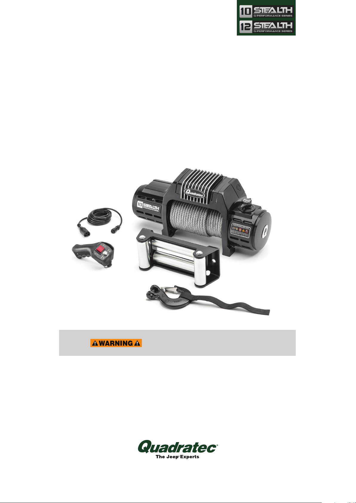
Rocker Switch
Red “Wireless”
Indicator Light
Remote
Control
Power Button
WIRELESS
MODE
NOTE:
The wireless remote will work
within a range of 10 feet from the
winch but may work farther distances
depending on physical obstructions and
other conditions. We do not recommend
using the wireless feature from the cab of
your vehicle. If you choose to winch from
the cab, please use the wired option for
safety and consistency.
THE POWER BUTTON MUST BE OUT FOR WIRED
CONTROL OF THE WINCH.
THE POWER BUTTON MUST BE IN FOR WIRELESS
CONTROL OF THE WINCH.
PRESSING AND RELEASING THE POWER BUTTON
WHILE THE WINCH MOTOR IS ROTATING WILL
IMMEDIATELY STOP ROTATION.

8
NOTE: The presence of a battery is NOT
required whenever using a“WIRED”
remote controller. But, a charged battery
is necessary when using a “WIRELESS”
remote controller. If the wireless mode
is not functioning properly, the battery
may need replacement.
Battery Replacement Procedure:
Remove the three (#1 size) Phillips head
screws that attach the winch controller
halves.
Carefully remove the old CR123A or
CR123 Lithium battery and replace with
new. Gently align and position the winch
controller halves together and fasten the
three Phillips head screws. Do not over
tighten! Test the winch “OUT” and “IN”
functions on the remote to ensure that
the remote is functioning properly.
Remote Controller Battery Replacement
Remove 3 Phillips
Head Screws
+ Positive
Battery End
CR123A
Lithium Battery

9
There are two positions of the clutch
handle. The Clutch is either “engaged” or
“free spooling”. Clutch allows operator
to manually engage or disengage the
spooling drum from the gearset using the
clutch lever.
Winch Clutch Operation Details
NEVER ENGAGE OR DISENGAGE CLUTCH IF THE WINCH IS UNDER
LOAD, THE WINCH ROPE IS UNDER TENSION OR THE SPOOL IS
MOVING IN ANY WAY.
Engaged Free Spool

10
NOTE: Our Patent Pending removable
Clutch Handle doubles as a “key”
that can be temporarily removed to
deter winch line theft, vandalism and
pranksters.
Once the Clutch Handle is removed, it
can be stored in the vehicles glove box
or console and used only when winching.
Clutch handle removal is optional.
Rotate Clutch Handle to the “FREE
SPOOL” position to reveal the set screw
that holds the handle in place. Using a
2.5 MM Allen wrench, back out the set
screw until the Clutch Handle lifts off but
do not remove the handle at this time.
Rotate the clutch selector to the
“ENGAGED” position. You may remove
the Clutch Handle now and keep it in
a safe place. We suggest keeping the
Clutch Handle somewhere in the vehicle,
Note: If the handle is not present when
winching is needed, a standard 3/8” drive
socket wrench extension can be used to
rotate the clutch selector mechanism.
US PATENT PENDING
Clutch Handle Removal (Optional)
DO NOT KEEP THE
CLUTCH HANDLE
ON THE WINCH UNLESS THE SET SCREW IS
FULLY ENGAGED TO SECURE THE HANDLE IN
PLACE.
Otros manuales para Q Series
1
Este manual sirve para los siguientes modelos
4
Tabla de contenidos
Otros manuales de Cabrestante de Quadratec

Quadratec
Quadratec Q-Performance Stealth Series Guía de configuración

Quadratec
Quadratec Q9500i Manual

Quadratec
Quadratec Q9000 Synthetic Manual

Quadratec
Quadratec Q Series Guía de configuración

Quadratec
Quadratec Synthetic Q10000c Manual

Quadratec
Quadratec Q-Performance Stealth Series Manual de usuario

Quadratec
Quadratec Q11000s Manual


