QRP Labs Ultimate3 Manual de usuario

Ultimate3: QRSS Labs Multi-mode QRSS Beacon Kit
PCB Revisions 3 and 4
1. ntroduction
Thank you for purchasing my third generation “Ultimate3” Multi-mode QRSS beacon kit This kit is capable
of automated transmission of a range of weak signal modes that are capable of worldwide HF propagation
using a fraction of a watt of RF output power The DDS module permits accurate, stable operation
anywhere on HF whilst plug-in low-pass-filter modules allow easy band changing
Recommended approach to building the kit: This is a simple design but there are a large number of
features which provide a great deal of flexibility Read this WHOLE manual and understand it! Follow
the construction section to build the kit Use a receiver connected to your PC, with a slow-signal decoding
program such as Argo, to monitor your signal, experiment and understand the various features before
connecting an antenna! Good performance depends on proper set up:, see the calibration section.
Please read the DDS module stability section 7! Do not miss this section, or your output signal may
be unstable and look horrible!
This assembly manual is to be read in conjunction with the operation manual!
The kit supports the following modes:
•QRSS mode (plain on/off keyed slow CW)
•FSK/CW mode (frequency shift keyed slow CW)
•DFCW mode (dual frequency CW, dit's and dah's on different frequencies)
•WSPR and WSPR-15 modes (Weak Signal Propagation Reporter)
•Slow-Hellschreiber (frequency shifted slow Hellschreiber)
•Hellshreiber (full-speed standard Hellschreiber, and half-speed Hellshreiber)
•CW (plain CW) and fast FSK mode
•Transmitter mode
•Customisable FSK patterns
Other features:
•DDS-controlled output frequency (through-pin DDS module, no SMD soldering required)
•Plug-in low pass filter boards (available for 10 HF and 2 LF bands)
•16-column x 2-row LCD with backlight, and two-button user interface
•User-programmable (callsign, message, speed, FSK, mode, etc ), settings stored in EEPROM
•GPS interface, for locking the frequency, timing and location information
•On-chip generation of WSPR encoded message (no PC required)
•WSPR maidenhead locator can be generated from GPS-derived latitude/longitude
•Selectable “frame” size, for stacked QRSS reception
•Plain CW callsign identifier at selectable interval
•Produces approximately 150mW RF output on 30m (lower output on higher frequency bands)
•Higher output power by fitting additional PA transistors and/or higher PA supply voltage
1

The transmitter is designed to be powered with 5V DC, which could come from a mobile phone charger,
wall wart, or even four 1 5V batteries connected in series with a suitable low dropout regulator Do not use
more than 6V: this may kill the microcontroller; the LCD may not work properly with more than 5V Best
results will be obtained with a well-regulated and well-smoothed 5V supply
2. Design
2

The ATmega328 AVR microcontroller (IC1) is pre-programmed with firmware to control the LCD, buttons,
and GPS interface The AD9850 Direct Digital Synthesis (DDS) module includes its own on-board 125MHz
crystal reference oscillator, and reconstruction filter components ready-mounted On/off keying is provided
by the BS170 transistor Q1, and power amplification by another BS170 transistor, Q2, producing over over
150mW from a 5V supply on 30m Finally standard 7-element low pass filter plug-in modules remove
harmonics of the transmission frequency
3. Parts List
3.1 Resistors
R1 100K preset potentiometer, for LCD contrast adjustment
R2 No resistor – space is provided on the PCB only for reducing LCD backlight brightness
R3 No resistor – space is provided for a 100K resistor, if you want to do AVR firmware upgrades
R4 No resistor – space is provided for a 220K resistor, for smoother contrast adjustment
3.2 Capacitors
C2, 3 22pF (ceramic, marking 22, or 220)
C1, 4, 5, 6 10nF (ceramic, marking 103)
C7 No capacitor – space is provided for future enhancements
3.3 nductors
L1 25 turns, FT37-43 core (black)
3.4 Semiconductors
Q1, 2, 3, 4 BS170 (note: only two are provided in the kit The other two may be added for more power)
D1 No diode – provided for use with relay-switched LPF board kit
IC1 Pre-programmed ATmega328 microcontroller
DDS AD9850 DDS module, including 125MHz reference oscillator and reconstruction filter
3.5 Miscellaneous
Two push buttons, S1 and S2
16-column x 2-row LCD (HD44780-compatible) with blue LED backlight
Printed circuit board, 80 x 37mm size
Wire for winding toroid
Socket for IC1
20MHz quartz crystal
Two 10-pin female header sockets
Two 4-pin female header sockets
16-pin female header socket
16-pin male header plug
Four 12mm nylon hex PCB spacers
Eight 6mm M3 screws
Relay RL0 – not supplied, provided for use with relay-switched LPF board kit
3

4. Construction
4.1 General construction tips
The kit comes as a main board, with pre-assembled DDS module, and a plug-in low-pass-filter module for
the desired band Since the low-pass filter module is a separate kit in its own right, please refer to
the separate instructions for constructing that kit.
Parts placement is defined by the printed legend on the PCB, so please observe it carefully, paying
particular attention to the correct orientation of the semiconductors
The PCB is quite small and the parts are close together You are recommended to use a low wattage iron
with a fine tip, and fine solder e g 1mm diameter or less Take care not to overheat the PCB and risk
damaging it A well-lit area and magnifying glass can assist Be careful not to bridge solder across closely-
packed connections Some of the joints are very close to each other I recommend checking with a DVM to
make sure no solder bridges have been inadvertently created
Note that components R2 and C7 are not required or supplied in the kit (R2 may be added by the builder if
lower LCD backlight brightness is desired) Q3 and Q4 are not supplied, additional BS170 transistors may
be installed here to increase the output power (see below) IC1 (the microcontroller) has an IC socket, in
case in future you wish to change the microcontroller e g for a firmware upgrade for new features, etc , or
in case you wish to program it yourself Sockets are provided for the DDS module and the low-pass-filter
module
4.2 Construction steps
Please refer to the parts placement diagram below
Pay special attention to the orientation of the semiconductors For IC1, the dimple in the PCB silkscreen
must be aligned with the dimple at the top of the IC socket and the IC
The order of construction is not important but a good principle to follow is to install the smaller components
first, so that the larger ones do not prevent easy access One suggested order of construction is described
below and I'd recommend following it carefully
4

NOTE: Photos below show PCB revision 1, but they are very similar!
1) Solder in the socket for C1.
To avoid confusion or mistakes later, align the
dimple at one end of the socket, with the
dimple illustrated on the PCB The dimple
should be at the end nearest the right-hand
edge of the PCB
2) Solder in all capacitors and the quartz
crystal (note there is no C7).
Be careful not to mix up the 22pF and 10nF
capacitors The two 22pF capacitors are the
ones on each side of the crystal
3) Fit and solder switches S1 and S2, if not
using off-board switches.
The switches are in a convenient location to
press with your left and right index fingers
when holding the module in your hands, with
the LCD facing you However, it is certainly
nicer to fit off-board switches as well, on a
front panel (see later “hardware options”
section)
4) Wind and install the toroid
The toroid can be mounted horizontally or
vertically I prefer the horizontal method as
there is enough space for it, and it keeps the
toroid away from the LPF module which is
plugged in above When winding the toroid,
remember that each time the wire goes
through the centre of the toroid counts as one
turn 35cm of wire should be enough for 25 turns Trim the ends of the wire, scrape the enamel off
and tin them with solder As an alternative to scraping the enamel off, the wire ends may be held in
a hot blob of solder on the iron tip for a few seconds, and the enamel will bubble away Check
continuity on the board with a DVM
5) Solder the sockets for the DDS module and
the low-pass-filter board.
Some care needs to be taken with the
alignment, to ensure that there is a good fit
when the plug-in boards are added One
method is to build the LPF kit board first, and
5

use the DDS and LPF boards plugged into the sockets, then solder the pins, to ensure correct
alignment
6) Fit and solder R1, the preset potentiometer
that sets the LCD contrast.
It is a slightly tight fit but apply pressure
carefully and evenly, and the pins of the
potentiometer will fit into the PCB perfectly
Adjust this potentiometer to the fully clockwise
position initially
7) Solder wire jumpers as shown in the
diagram below (red wires circled in
yellow), depending on your requirements.
These can be made from offcuts from the
other components e g capacitor leads When
installing these wire jumpers, I find it
convenient to install them as a small semi-
circular arch, perhaps 5mm high off the board,
as pictured This is so that later, if they need
to be removed (for different hardware options configuration), a convenient alternative is to just cut
them using wire cutters PCB Rev 3/4: please follow diagram below, not photo!
The W0-W1 and W2-W3 jumpers hard-wire the LPF into the circuit Note that when a relay is fitted
at RL0, you do NOT connect these two jumper wires The relay is part of another kit, the relay-
switched LPF board, that expands the capability of the U3 kit to sequence through up to 6 different
bands
If R2 is installed, in order to reduce LCD brightness, then connect A1-A2 instead of A0-A1 (see
“hardware options” section below)
You may also install a jumper at the +PA and +5V connections at the bottom of the picture below, in
order to power the power amplifier (PA) with the 5V supply You should leave out this jumper if you
intend to run the PA at a higher voltage See more details in the “Hardware options” section below
6

Also pay attention to the jumpers at R3 and R4 on the right-hand side of the diagram R3 is an
optional resistor, to be fitted to enable in-circuit-programming for those wishing to update their own
firmware and having the necessary equipment
f you do not fit a 100K resistor for R3, then you must fit a wire jumper here as shown.
Resistor R4 is an optional resistor, which is in series with the top of the contrast adjustment
potentiometer R1 and +5V Typically the contrast voltage required is less than 1V and the
adjustment is rather sensitive If you wish, you can fit a 220K resistor in this position, which will
make the contrast potentiometer less sensitive to adjust
f you do not fit a 200K resistor for R4, then you must fit a wire jumper here as shown.
8) Solder in transistors Q1 and Q2.
If you have purchased additional transistors
for Q3 and Q4 to increase the power output,
then Install these now too
The transistors are located at the edge of the
PCB with their flat side outwards This is to
allow easy attachment of a heatsink if desired (for higher voltage and hence higher power
operation)
9) nstall two 16-way connectors on the main PCB and LCD.
Either way is fine, but my recommendation for
installing the LCD connectors, is to use the
female (socket) connector on the PCB side
and the male (plug) on the LCD Be sure to
solder the socket to the reverse of the
main U3 PCB!! Not the top side! If you bolt
together the LCD module and the PCB, with
the 16-way connectors in place but not
7

soldered, then you will be able to ensure perfect alignment Use the eight 6mm M3 screws, and four
12mm nylon hex spacers, to bolt the PCB to the LCD
The combined 16-way plug and socket when
mated together, have a height of a little under
12mm Therefore it is necessary to have a
gap somewhere
My suggested method is illustrated to the right
here I suggest closely mating the plug and
socket Leave the gap between the male header (plug) and the U3 PCB I have found this method
to work successfully
4.3 Module assembly
First the microcontroller IC1 should be inserted in its socket Be sure to align the microcontroller chip
correctly, the dimple on the chip must be at the same end as the dimple on the socket, and the dimple on
the silkscreen legend on the PCB
Next, plug together the three modules as shown in the following photographs
Ensure that the DDS module is inserted the correct way round The Low Pass Filter kit module should be
plugged in with the “Out” legend aligned next to the RF Output connector of the main PCB (see photo)
mportant! Upon power-up, you will need to adjust the contrast potentiometer R1 to view the LCD
properly. Turn it fully clockwise to start with (before applying power). Then turn it gradually anti-
clockwise until the displayed text looks correct.
4.4 Notes concerning the DDS module
a) You will notice that the DDS module has a square, blue plastic adjustment preset potentiometer This
adjusts the threshold for the DDS chip comparator that turns its 1V p-p sine wave into a square wave to
drive the microcontroller Adjusting it will change the duty cycle of the DDS square wave You should not
need to adjust this potentiometer, as I have already adjusted it individually, when I tested every DDS
module before putting it in a kit However, some builders have noted that the potentiometer needs to be
adjusted slightly for best output waveform on 10m (28MHz) The adjustments needed are extremely slight,
the potentiometer setting is very sensitive
b) The module uses the AD9850 DDS chip The module is officially rated for output from DC to 40MHz
You may want to test it at higher frequencies than that In theory the chip could output up to 62 5MHz (half
the 125MHz reference clock frequency), but the output amplitude and spectral purity will deteriorate
8

c) It is normal for the 125MHz reference oscillator (metal can on the right) to get hot in operation
5. Hardware Options
5.1 Explanation of connections
The table to the right details the
purpose of the connection points
around the right-hand and bottom
edges of the PCB The pin-spacing is
0 1-inches and a suitable connector
could be used if desired These are
further described in the following
sections
Note that the cluster of connections at
the left board edge are for fitting the
connector to the relay-switched LPF board kit They can be ignored for now
Connections A0, A1 and A2 allow options concerning the LCD backlight, as described below For basic
operation, simply connect A0 and A1
5.2 Connection for basic operation
For the most basic operation of this kit as QRSS transmitter using 5V supply, it needs only a power supply
and RF output connection
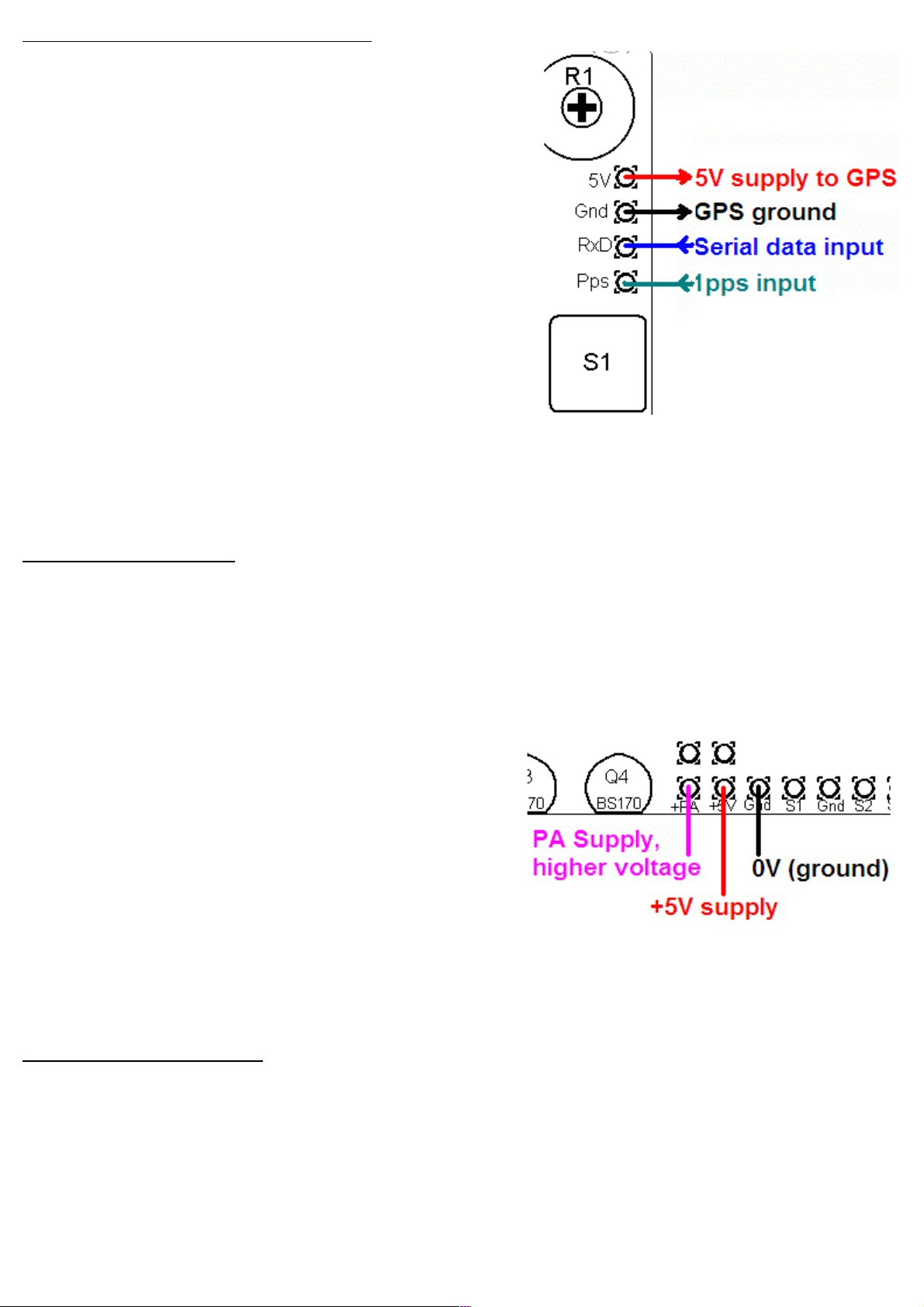
To allow use of a higher voltage
supply for the PA, the PA voltage is
not connected to +5V on the PCB So
to run the transmitter using the 5V
supply, be sure to connect a wire
between the +5V and PA pins, as
shown by the short red vertical line in
the diagram (right)
5.3 Alternative button mounting option
If you wish you may use an external pair of buttons to control
the kit The button input signals are available at the edge of
the board, labelled S1 (left button) and S2 (right button) The
buttons should be of the push-to-make variety The left button
should be connected between the S1 signal and ground;
similarly the right button should be connected between the S2
signal and ground
9
Label Group Description
5V GPS +5V supply to GPS module
Gnd GPS Ground connection to GPS module
RxD GPS Serial data input from GPS module
Pps GPS 1 pulse per second input from GPS module
Tune Future No connection – for future enhancements
Sin Options RF output from DDS, 1V p-p sinewave
Out Options RF output from DDS, 5V p-p squarewave
S2 Buttons Optional external button S2, switch to Gnd
Gnd Buttons Ground for optional external buttons
S1 Buttons Optional external button S1, switch to Gnd
Gnd Power Ground connection to Power supply
+5V Power +5V power supply
+PA Power PA power supply – may be connected to +5V
Gnd RF Ground for RF output
RF RF RF output
5.4 Optional connection of GPS module
A GPS module may be connected to the kit, to provide
frequency stability, accurate time, and latitude and longitude
which can be converted to Maidenhead locator format for
encoding in the WSPR message transmission
Check that your module is powered from 5V Many modules
specify a 3 3V supply – in this case you will need to provide
an external 3 3V voltage regulator Where a 3 3V GPS
module is used, the serial data and 1 pulse-per-second (pps)
inputs are not a problem for the 5V microcontroller on the kit
PCB – no voltage level conversion is required
In cases where the location information is not required
(modes other than WSPR) or you wish to enter it manually,
the serial data input can be left unconnected The 1 pps input
is enough for the frequency lock function Note that the
frequency locking function can only operate if you have selected a wait period between message
transmission (i e a non-zero “Frame” parameter)
See operation instructions for details on how to configure the GPS interface
5.5 Higher power output
The kit provides around 150mW of output power using a 5V supply and a single BS170 transistor
(depending on the band) The transistor gets slightly warm to the touch If higher output powers are
desired, this can be achieved by using a higher supply voltage for the Power Amplifier (PA) The
microcontroller must still be run at a voltage not exceeding its 5 5V rating (5V is recommended) To
facilitate running the PA at higher voltages to provide more power, the PA supply connection is a separate
pin
At higher supply voltages and power outputs, the heat
dissipation in the BS170 will increase and its temperature
will be higher Provision is made on the PCB for two more
transistors in parallel with the first This will slightly increase
the power output even at 5V supply, but more importantly
at higher voltages it should share the heat dissipation
between the devices
It may be necessary to fix a heat sink to the transistors if the temperature rise is excessive The transistors
are sited near the edge to the board to facilitate this Experiment is needed in this area, with PA voltages
up to perhaps 12V
5.6 Audio frequency output
The kit can be used to generate audio tones for feeding to an SSB transceiver etc In this case you can
simply set the output frequency to the desired audio frequency, and feed the “RF” output to the
microphone input It is very important to note that this output is a just a 5V peak-to-peak square wave – to
connect it to a microphone input (for example) you will need to reduce the signal amplitude considerably
In testing, I used a potential divider made of an 18K resistor and a 10-ohm resistor to ground The mic
input was connected across the 10-ohm resistor and provided a suitable signal amplitude
10
Tabla de contenidos
Manuales populares de Unidad de control de otras marcas

Festo
Festo Compact Performance CP-FB6-E Manual de lista de piezas

Elo TouchSystems
Elo TouchSystems DMS-SA19P-EXTME Manual de usuario

JS Automation
JS Automation MPC3034A Manual de usuario

JAUDT
JAUDT SW GII 6406 Series Guía rápida

Spektrum
Spektrum Air Module System Manual de usuario

BOC Edwards
BOC Edwards Q Series Manual de usuario


