Production Basics 3000 Manual de usuario

Production Basics, Inc. Massachusetts, USA 800.318.2770 617.926.8100 Fax: 617.926.8010 www.pbasics.com
ASSEMBLY MANUAL
ASSEMBLY VIDEOS AVAILABLE ON-LINE http://video.pbasics.com
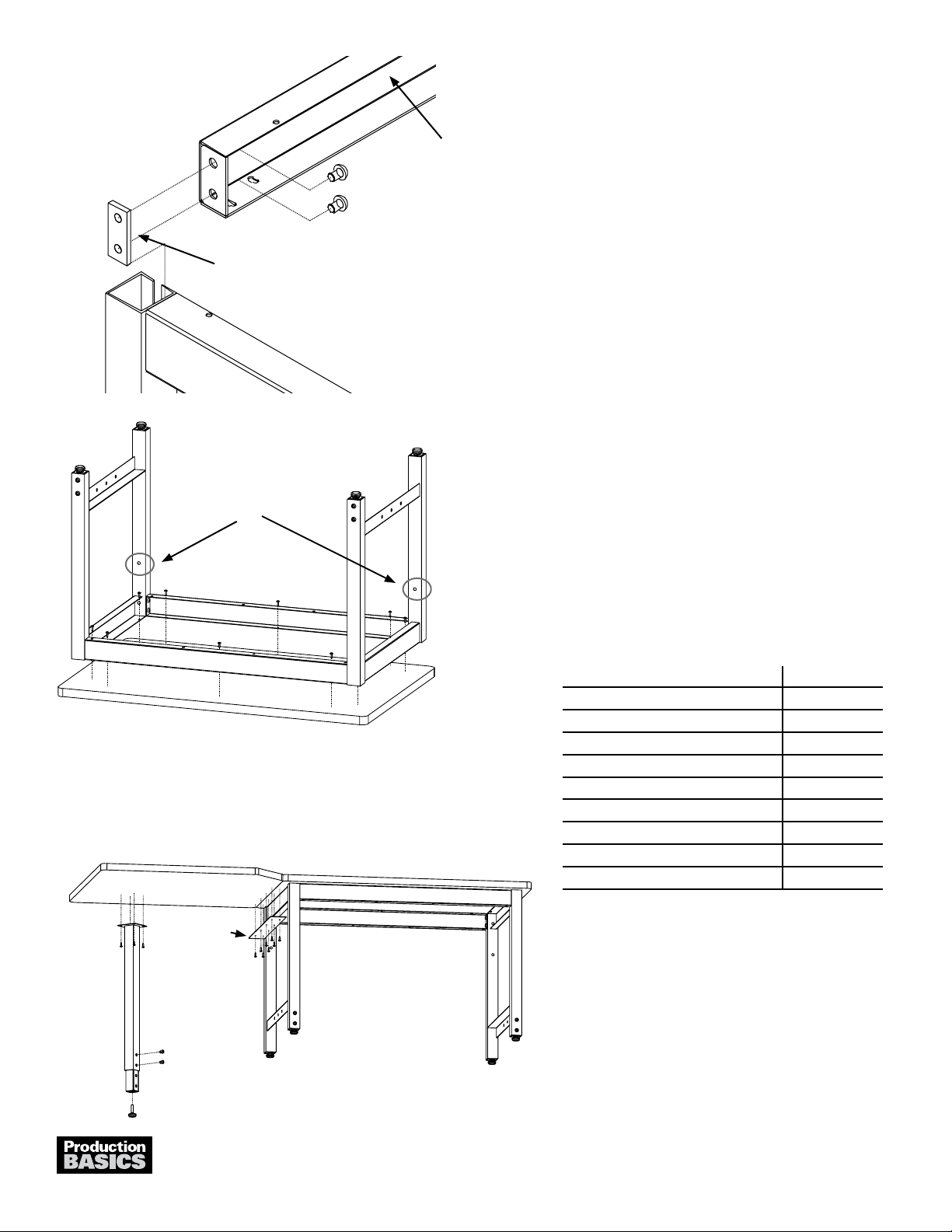
1. Open the cartons and identify the left and right Frame
Legs and RTW Support Rail. Position Frame Legs so
that mounting holes for Uprights are at the back of the
RTW Table. Frame Legs have a horizontal open channel
that faces inward.
2. Screw the levelling feet all the way into the leg adjusters.
3. Slide leg adjusters into bottom of Frame Legs. Determine
desired table height and secure position by inserting two
(2) Basic Bolts. Adjust leveling feet if necessary.
Assembly Tips
• Review entire instruction manual before proceeding.
• Production Basics nameplate indicates front of frame.
• Legs are adjustable in 2-inch increments between 30-36 or 30-42
inches high, depending on products ordered.
• Don’t be a slave to gravity-recruit a co-worker to help you install and
correctly position components and accessories.
• References to ‘Left’ and ‘Right’ are oriented as if you were facing the
front of the workstation.
• Need help? Call Assembly Support at 800.318.2770.
RTW TABLE
Item Numbers 3000-3115
Workstations
RTW Table with optional accessories
Basic Bolt
Wood Screw
Chrome Mounting
Plate
Mounting holes for Uprights
must be at back of Frame Leg.
RTW Support Rail
(channel faces inward)
Right Frame Leg
(channel faces inward)
PARTS AND HARDWARE QUANTITY
Frame Legs (left and right specic) 2
Leg Adjusters 4
RTW Support Rail 2
Chrome Mounting Plate 4
Worksurface 1
Leveling Feet 4
Wood Screws 12
Basic Bolts 16
7/32 Allen Wrench 1
Other Items Needed (not included)
Phillips head drill or screwdriver
Rubber mallet
Level
Tape Measure
1602A301
1

Need Help? Call Assembly Support at 800.318.2770
1. Insert two (2) Basic Bolts into adjustable leg, determining
height. Screw in Leveling Foot
2. Insert four (4) wood screws through connection plate
and into the underside of the worksurface on the existing
RTW Table. Repeat for other connection plate on
opposite RTW Table.
3. Place the corner laminate worksurface in between the
workstations. Secure with wood screws though the
connection plate.
4. Use wood screws to attach adjustable leg to underside of
worksurface 1” from edge.
• Note: Add-on Corner requires two (2) RTW Tables
for proper assembly. Assemble RTW Tables
before assembling Add-on Corner.
PARTS AND HARDWARE QUANTITY
Height Adjustable Leg (2 pieces) 1
Leveling Foot 1
Connection Plates 2
Laminate Worksurface 1
Basic Bolts 2
Wood Screws 20
7/32 Allen Wrench 1
Other Items Needed (not included)
Phillips head drill or screwdriver
RTW ADD-ON CORNER
Item Numbers 3418-3519
Chrome Mounting Plate
Left Back
Mounting holes for Uprights
must be at back of Frame Leg.
RTW Support Rail
Connection Plate
4. Locate Support Rail. Loosely attach the Chrome
Mounting Plate to the outside of the Support Rail with
two (2) Basic Bolts using Allen wrench provided.
5. Slip the Chrome Mounting Plate into the slot on the
frame leg as shown. The leg will be between the Chrome
Mounting Plate and the Support Rail. Repeat for all sides
and tighten bolts.
6. Invert the assembled RTW frame onto the underside of
the worksurface. Position the worksurface and frame so
that it is ush with the back of unit with equal overhang,
left and right.
7. For laminate and hardwood worksurfaces, attach the
worksurface to the frame by drilling wood screws through
the pre-drilled holes in the Support Rails and Frame
Legs, then into underside of worksurface. For other
surfaces, specic instructions are included with your
worksurface. Turn RTW Table right side up.
1602A301
2

ASSEMBLY MANUAL
Production Basics, Inc. Massachusetts, USA 800.318.2770 617.926.8100 Fax: 617.926.8010 www.pbasics.com
1. Insert Ground Bolt through top of worksurface through pre-drilled hole.
2. Slip ground wire over bolt underneath the worksurface. Add washer
and nut then tighten.
3. Ground other end of wire to electrical ground.
4. For additional information on grounding, contact your company’s ESD
manager or the ESD Association at 315.339.6937, www.esda.org.
GROUND BOLT
For ESD Laminate Worksurfaces and Shelving
PARTS AND HARDWARE QUANTITY
Ground Bolt 1
Ground Wire 1
Washer 1
Nut 1
1602A301
3

Production Basics, Inc. Massachusetts, USA 800.318.2770 617.926.8100 Fax: 617.926.8010 www.pbasics.com
ASSEMBLY MANUAL
ASSEMBLY VIDEOS AVAILABLE ON-LINE http://video.pbasics.com
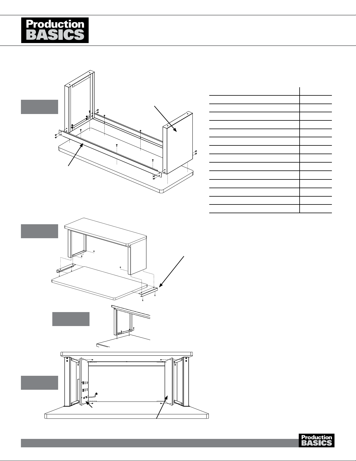
1. Attach Cross Bars to End Supports with nuts and bolts
as shown.
2. Invert laminate shelf and position frame from step #1 on
top with a 3/8” overhang on left and right sides and back.
Front will have a 3 3/8” overhang. Ensure the t-mold
seam is positioned in the back and the Production Basics
ID label is on the front.
3. Use wood screws to secure frame to shelf. Set aside
until step 5.
4. Slide End Support Mounts over right and left edges of
worksurface on assembled RTW Table with studs facing
up.
a. For other worksurface thicknesses that cannot use
end support mounts. Attach directly through End
Supports from inside through worksurface. Skip to
Step 8.
5. Flip shelf assembly from step #3. Position holes in
bottom of End Supports over End Support Mounts.
Secure nuts onto studs to hold Riser Shelf to end
support mounts.
6. Slide Riser Shelf toward rear of bench. End Supports
should be approximately 3/4” from rear edge of bench.
7. Secure Riser Shelf to underside of bench using wood
screws through end support mounts.
8. Install End Support Covers onto inside of end supports
with tek screws. If installing Power Panel (Item #8328 or
8329), do so on inside left of Riser Shelf, in place of the
left end support cover.
RTW RISER SHELF & POWER PANEL
Item Numbers 8467-8474, 8328-8329
PARTS AND HARDWARE QUANTITY
End Supports 2
Cross Bars 2
End Support Mount 2
End Support Cover 2
Laminate Shelf 1
Tek Screws 8
Wood Screws 14
Kep Nut 12
1/4-20 Screws- 1/2” 8
Power Panel (if ordered) 1
5/32 Allen Wrench 1
Other Items Needed (not included)
Phillips head drill or screwdriver
Tape Measure
Shelf Underside
Cross Bar
End Support
End Support Mounts
Optional Power Panel
End Support Cover
Steps 1-3
Steps 4-7
Step 4a
Steps 4-7
1602A301
4

Production Basics, Inc. Massachusetts, USA 800.318.2770 617.926.8100 Fax: 617.926.8010 www.pbasics.com
ASSEMBLY MANUAL
ASSEMBLY VIDEOS AVAILABLE ON-LINE http://video.pbasics.com
1. Use wood screws to attach Supply Compartment Ends
to underside of worksurface. Make sure the side without
a ange is positioned forward the outside of the the
Compartment ends are ush with RTW Table legs.
2. Attach Supply Compartment Back to the Compartment
Ends using nuts and bolts. Secure with wood screws
through the top ange on the underside of the
worksurface.
3. Slide Supply Compartment Base on to the Ends/Back
assembly. Make sure the lip is in the front of the table.
Secure with nuts and bolts.
SUPPLY COMPARTMENT
Item Numbers 8497-8499
PARTS AND HARDWARE QUANTITY
Supply Compartment Ends 2
Supply Compartment Back 1
Supply Compartment Base 1
Wood Screws 9
Kep Nuts 10
1/4-20 Bolts- 1/2” 10
Other Items Needed (not included)
Phillips head drill or screwdriver
Step 1
Step 2
Step 3
1602A301
5

Production Basics, Inc. Massachusetts, USA 800.318.2770 617.926.8100 Fax: 617.926.8010 www.pbasics.com
ASSEMBLY MANUAL
ASSEMBLY VIDEOS AVAILABLE ON-LINE http://video.pbasics.com
1. Align Modesty Panel onto rear of RTW frame as shown.
2. Install 3/8- 16 bolts into top slots on Modesty Panel and
RTW Frame. Lightly secure using 3/8- 16 Kep Nuts- do
not tighten
3. Install lower brackets and kep nuts into bottom slots of
Modesty Panel and hook around RTW Frame. Lightly
attach- do not tighten.
4. Slide Modesty Panel up until the top ange is tight
against the Support Rail. Tighten bolts and kep nuts into
top slots of Modesty Panel and RTW.
5. Tighten all nuts and bolts.
6. Attach Tek screw into center of RTW Modesty Panel and
then into Support Rail from back of workbench to secure
panel to RTW.
RTW MODESTY PANEL
Item Numbers 8750, 8751, 8752, 8753
PARTS AND HARDWARE QUANTITY
Modesty Panel 1
Lower Mounting Bracket 2
5/16- 18 Kep Nuts 2
3/8- 16 Kep Nuts 4
3/8-16 Bolts- 2 3/4” 4
5/16 Flat Washer 2
#8 Tek Screw- 1/2” 1
Other Items Needed (not included)
Phillips head drill or screwdriver
Steps 1-5
Step 2
1602A301
6

Production Basics, Inc. Massachusetts, USA 800.318.2770 617.926.8100 Fax: 617.926.8010 www.pbasics.com
ASSEMBLY MANUAL
ASSEMBLY VIDEOS AVAILABLE ON-LINE http://video.pbasics.com
• Note: For correct installation of Upright, ensure
the worksurface is positioned ush with back of
the workstation.
1. Attach the mounting plate by inserting one (1) 3/8-16 x 2
3/4”” bolt and washer through both pre-drilled holes on
the back of each Frame Leg, then through holes on the
mounting plate. Secure with nut. For correct installation,
position the short ange of the mounting plate around
the inside corner of the Frame Leg, as shown. Repeat for
other side of workstation.
2. Insert a Basic Bolt into each hole on the front of the
mounting plate. Secure with Basic Nut with grooves
facing the mounting plate. Turn only one revolution.
Repeat for other mounting plate.
3. Position Uprights against the two (2) Basic Nuts on each
mounting plate. Turn Basic Bolts 90 degrees clockwise to
grip. Tighten the Bolts. Repeat for other Upright. Ensure
Uprights make contact with both Basic Nuts.
PARTS AND HARDWARE QUANTITY
Uprights 2
3/8-16 x 2 3/4” Bolts 4
3/8-16 Kep Nuts 4
3/8 Washers 4
Basic Bolts 4
Basic Nuts 4
Mounting Plates 2
7/32 Allen Wrench 1
UPRIGHTS WITH MOUNTING KIT (for RTW, PedSys & Easy-Lift 4-post)
Item Numbers 8530, 8531, 8535, 8536 ACCESSORIES
1602A301
7

Production Basics, Inc. Massachusetts, USA 800.318.2770 617.926.8100 Fax: 617.926.8010 www.pbasics.com
ASSEMBLY MANUAL
ASSEMBLY VIDEOS AVAILABLE ON-LINE http://video.pbasics.com
• Note: To install Overhead Arms only, perform
steps 3 & 4.
1. Unscrew 2 security screws on face of light unit.
Remove plastic diffuser.
2. Insert T8 light bulbs into xture. Plug light in to test
correct installation of bulbs. Replace diffuser and security
screws.
3. Insert two (2) Basic Bolts into mounting plate on
Overhead Arm. Secure with Basic Nut with grooves
facing the back of the mounting plate. Turn only one
revolution. Repeat for other Overhead Arm.
4. Insert Basic Nuts attached to Overhead Arm mounting
plate into frame channel of workstation or Uprights and
turn Basic Bolt 90 degrees clockwise to grip. Top of
mounting plate should be ush with top of frame cross
member. Tighten the bolts. Repeat for other Overhead
Arm.
5. Insert 4 Basic Bolts from bottom into light mounting plate.
Secure with 4 Basic Nuts with grooves facing down. Turn
only one revolution.
6. Position light unit with cord facing the frame. Insert Basic
Nuts attached to light unit into Overhead Arm channel
and turn Basic Bolt 90 degrees clockwise to grip.
7. Slide the light unit to the desired position. Tighten the
bolts. Slide End Caps onto front ends of Overhead Arms.
OVERHEAD LIGHT & OVERHEAD ARMS
Item Numbers 8500, 8504, 8505, 8510, 8512, 8514, 8516, 8518, 8538 ACCESSORIES
PARTS AND HARDWARE QUANTITY
Overhead Arms 2
End Caps 2
Basic Bolts 4 (Arms only)
8 (With light)
Basic Nuts 4 (Arms only)
8 (With light)
Light Unit 1
7/32 Allen Wrench 1
Other Items Needed (not included)
24” T8 bulb for 36” 3
36” T8 bulb for 48” 3
48” T8 bulb for 60” & 72” 3
Phillips head screwdriver
Tape Measure
Diffuser
Overhead Arm
mounting plate
Security Screws-
REMOVE BEFORE
STARTING ANY
ASSEMBLY
Light Mounting Plate
Overhead Light on Frame
Overhead Light on Uprights
Security Screws-
REMOVE BEFORE
STARTING ANY
ASSEMBLY
1602A301
8

Production Basics, Inc. Massachusetts, USA 800.318.2770 617.926.8100 Fax: 617.926.8010 www.pbasics.com
ASSEMBLY MANUAL
ASSEMBLY VIDEOS AVAILABLE ON-LINE http://video.pbasics.com
• Note: To install Overhead Arms only, perform
steps 3 & 4.
1. Install light mounting brackets on each end of light using
a 3-Lobe Knob and washers. Mounting bracket should be
ush with the top of the light unit.
a. To lock in the fixed position, install using 3-Lobe
Knob and sheet metal screws.
2. Insert Basic Bolts from bottom of each light mounting
bracket and secure with Basic Nuts. Turn only one
revolution. Repeat for other bracket.
3. Insert two (2) Basic Bolts into mounting plate on
Overhead Arm. Secure with Basic Nut with grooves
facing the back of the mounting plate. Turn only one
revolution. Repeat for other Overhead Arm.
4. Insert Basic Nuts attached to Overhead Arm mounting
plate into frame channel of workstation or Uprights and
turn Basic Bolt 90 degrees clockwise to grip. Top of
mounting plate should be ush with top of frame cross
member. Tighten the bolts. Repeat for other Overhead
Arm.
5. Position light unit with cord facing the frame. Insert Basic
Nuts attached to light unit into Overhead Arm channel
and turn Basic Bolt 90 degrees clockwise to grip.
6. Slide the light unit to the desired position. Tighten the
bolts. Slide End Caps onto front ends of Overhead Arms.
7. To adjust angle, loosen the 3-lobe knob on each end of
the light and tilt to desired angle. Tighten knobs.
OVERHEAD LIGHT, WITH DIMMER
Item Numbers 8900, 8901, 8902, 8903, 8904, 8905, 8906, 8907, 8908 ACCESSORIES
PARTS AND HARDWARE QUANTITY
Overhead Arms 2
End Caps 2
Basic Bolts 4 (Arms only)
8 (With light)
Basic Nuts 4 (Arms only)
8 (With light)
Light Unit 1
Light Mounting Brackets 2
7/32 Allen Wrench 1
3-Lobe Knob 2
1/4” Washer 2
Tek Screw 4
Other Items Needed (not included)
Phillips head screwdriver
Tape Measure
Step 1
Steps 2-7
Step 1a
1602A301
9

Production Basics, Inc. Massachusetts, USA 800.318.2770 617.926.8100 Fax: 617.926.8010 www.pbasics.com
ASSEMBLY MANUAL
ASSEMBLY VIDEOS AVAILABLE ON-LINE http://video.pbasics.com
• Note: Install Overhead Arms (sold separately)
before Tool Trolley System.
1. Insert Basic Bolts into hole on Tool Track and secure
with Basic Nut.
2. Position Track spanning the width of the Overhead Arms.
Insert the Basic Nut into the Overhead Arm channel, turn
bolt 90 degrees and tighten.
3. Ensure an end cap is secure on each end of the Track
and there is a ‘brake’ positioned on each end of the
track.
TOOL TROLLEY SYSTEM
item Numbers 8339, 8340, 8343, 8346
PARTS AND HARDWARE QUANTITY
Tool Track 1
Trolley with clip 1
Trolley Brake 2
Basic Bolts 4
Basic Nuts 4
End Caps 2
7/32 Allen Wrench 1
Tool Trolley System on Frame
Tool Trolley System on Uprights
End Cap
Trolley with clip
Brake
Tool Track
1602A301
10
Otros manuales para 3000
1
Este manual sirve para los siguientes modelos
1
Tabla de contenidos
Otros manuales de De oficina de Production Basics