Production Basics, Inc. Massachusetts, USA 800.318.2770 617.926.8100 Fax: 617.926.8010 www.pbasics.com
ASSEMBLY VIDEOS AVAILABLE ON-LINE http://video.pbasics.com
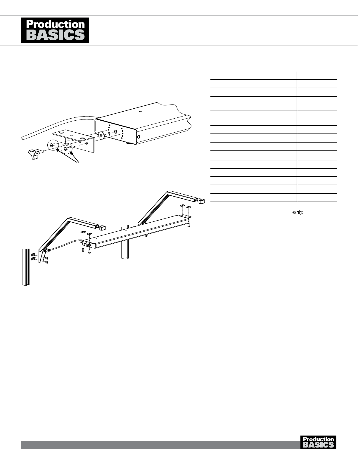
1. Insert two (2) Basic Bolts into pre-drilled holes
determining height. Repeat for other C-Leg.
2. Insert bolts into each hole at back of leg. Secure with
nut. Turn only one revolution. Repeat for other C-Leg.
3. Choose a leg for the right side of the station (as shown).
Attach Top Bracket to the inside of the C-Leg with tek
screws. This forms a shelf for the Worksurface Support
Rails. Repeat for other C-Leg.
4. Insert Basic Bolt from bottom into holes on Top
Bracket. Secure with nut. Turn only one revolution.
Repeat for left C-Leg with opposite bracket, for left
side of station.
a. If assembling Back-to-Back Stand Alone,
Back-to-Back multiple, or Side-by-Side Stations
prepare ALL C-Legs according to steps 1-4.
b. Quad and Side-by-Side Stations include one (1)
2C-Leg in place of two (2) C-Legs. Position the
2C-Leg in between adjacent stations (as shown).
5. Screw the Leveling Feet into bottom of C-Legs and
Frame. Use rubber mallet to tap End Caps into frame
and C-Legs.
a. For Side-by-Side & Quad Stations, end caps are not
used where frames meet.
b. If you have ordered casters, lock the caster and
turn the caster stem all the way into the leg until you
can no longer see the caster stem. Ensure caster is
completely tightened.
6. Lay Frame on a at, level surface, channel side up.
a. For Side-by-Side Stations, lay Frames next to each
other.
7. Insert Basic Nuts at back of leg into frame channel and
turn Basic Bolt 90 degrees clockwise to grip (see image
in Assembly Tips on page 1). Position C-Leg so that it
is parallel to vertical channel and ush with bottom of
frame. Tighten the bolts. Repeat with other C-Leg or
2C-Leg as applicable. Stand the station upright.
8. Place Worksurface Support Rails perpendicular to
Top Brackets, channel side down, on top of nuts (as
shown). Turn Basic Bolt 90 degrees clockwise to grip.
Tighten the bolts. Repeat for both sides of station and all
Worksurface Support Rails. 30”D C-Leg Stations have
two (2) Worksurface Support Rails; 36”D C-Leg Stations
have three (3).
9. Center the laminate worksurface on top of the
Worksurface Support Rails with T-mold seam at the
back. Ensure it is ush against the Frame. Attach the
worksurface from underneath with wood screws through
holes in Worksurface Support Rails
a. If assembling Back-to-Back Stations, repeat steps
7–9 for the other side of the configuration.
b. For different worksurfaces materials, an Assembly
Manual is included.
10. Check all attachments and give all the bolts a nal
tightening.
Worksurface Support Rail
2C Leg - Middle
Frame
C Leg - Right
Top Bracket
30”D Workstation
36”D Workstation
Steps 1-4
Step 4-7
Step 5a
Step 5b
Steps 8-9
see inset for detail