General Instrucons for both Mode 1 & 2
Signal Connecons
To preserve RF screening integrity, the signal connecons to the amplier should be made using
good quality coaxial cable and connectors. This is parcularly important with DTT to minimise the
ingress of impulsive electrical interference. The use of cable benchmarked under the CAI scheme
is recommended.
Crimp F connectors, used in accordance with the manufacturer’s instrucons, will give the best
results. The importance of achieving the sound braid connecons cannot be over-stressed.
Connectors should be ghtened with a spanner, not le nger-ght. Unused inputs and outputs of
this amplier do not need to be terminated.
Power Supplies
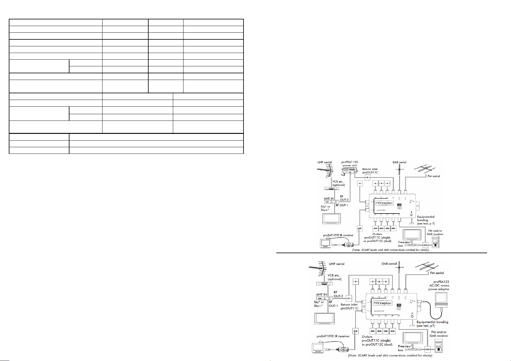
• PROPSU112X - 12V power unit connected anywhere in the UHF return feed (i.e. in the line
between RF OUT-2 of the Sky receiver and the amplier’s UHF input) Fig.2(a);
• PROPSA125 - a local AC/DC mains power adaptor connected to the DC power port, as in Fig.2
(b). The adaptor doesn't need to be regulated but does needs to have a standard 2.1mm DC
connector with the correct polarity (centre pin +ve). If a 3rd party adaptor is to be used its
output should conform to the requirements given in the technical data secon (page 8).
When using this opon the UHF input must be directly connected to the Sky receiver RF OUT-
2, since the 9V second outlet power needs to be sensed at the UHF input to switch the
amplier to Mode 2. The current drawn from the Sky receiver in this conguraon is very
small (typically 3-5mA).
Mains Power Supply
Any xed wiring installed to supply power for this amplier should comply with BS7671 (IEE wiring
regulaons) and, where relevant, Part P of the building regulaons. Refer to the instrucons
provided with the power supply unit for other safety informaon.
Spling outputs
As with any mul-way amplier the output signals can be split as illustrated in Fig1(b) to provide
addional outlet points. The PROcepon PROSPL204 splier is suitable for this in Mode 1 and
introduces approximately 4dB inseron loss. Spling outputs in Mode 2 is not recommended,
since it is not possible to provide individually protected eye power to the split outputs.
Signal levels
This amplier has relavely low forward gain gures and assumes that adequate input signal levels
will be available from properly installed aerials. The amplier gains are sucient to compensate
for addional distribuon cable losses in a typical domesc-scale systems whilst avoiding the
intermodulaon and other overload problems which result from the use of excessive gain.
Recommended minimum and maximum signal levels for each of the frequency bands are given in
the Technical data secon on page 8. Parcular aenon should be paid to the input VHF radio
signal levels. In city areas, very strong signals are oen received and it may be necessary to use
aenuators on one or both of the VHF inputs to avoid overloading the amplier.
Outlet plates
The use of outlet plates is recommended to provide a professional standard of nish to the
distribuon system. PROcepon’s screened outlet plates are recommended for use with this
amplier. The diplexed TV and radio plate (PROOUT12C) allows both TV and radio equipment to
be connected simultaneously to an outlet point. Single outlets (PROOUT11C) may also used and
will allow either TV or radio equipment to be used. The system diagrams in Fig.1&2 show both
types of plate in use.
In Mode 2, a PROOUT11C plate may also be used to provide the UHF return input connecon from
the Sky receiver, as illustrated in the diagrams in Fig.2.
Installaon locaon and xing
Choose a locaon for the amplier which is dry and not subject to prolonged ambient temperature
condions of less than -10°C of more than +40°C. Fix the unit to a sound vercal surface such as a wall
or equipment mounng board. Venlaon gaps of at least 50mm should be le around the front and
all sides of the unit. More clearance will be required around sides where cables are connected.
Do not install the amplier or its associated power unit where they may become smothered with
curtains or other so furnishing fabrics. When installing the amplier and power unit in a roof space,
ensure that they will not come into contact with thermal insulaon material.
System Equipotenal Bonding
A bonding terminal is provided on the amplier for use where necessary. Distribuon systems
supplying signals to more than one household should comply with he safety requirements of BS EN
60728-11. This eecvely requires earthed equipotenal bonding of the system. The use of isolated
outlet plates is no longer recommended since they compromise screening integrity and allow ingress of
interference.
Advanced Conguraon Features
Note: access to the features described in this secon involves opening the unit. The procedures below should only be carried out by a
competent person, preferably under workshop condions.
• UHF input line-power (preamplier power): where equipment (such as an aenuator) connected
to the UHF input might be damaged by the presence of the 5V output, or may cause the 30mA
current rang to be exceeded, the input line-power can be permanently disabled by removing the
internal LINE-POWER jumper.
• Forced Mode 2 operaon: where Mode 2 operaon is desire, but it is impraccable to connect a
Sky receiver directly to the UHF input to provide a 9V sense voltage. The unit can be forced into
Mode 2 by placing a jumper link on the 2-pin header labelled FORCE MODE 2. Since UHF input line
-power will not usually be required in Mode 2, the exisng LINE-POWER jumper can simply be
moved to the FORCE MODE 2 header posion. Forced Mode 2 operaon is only relevant when a
local power unit is in use, connected to the DC power port.
• Access: to open the unit remove the four corner screws from the rear cover. Separate the two
halves of the moulded cover and withdraw the screened amplier assembly, together with the
aached DC port connector. Remove the top metal lid (this is the side with the LED). One side of
the PCB is now exposed. Take great care not to disturb any of the coils, as this could de-tune the
input lters. The LINE-POWER jumper is located just above the LED; the Force MODE 2 jumper is
in the boom right-hand corner of the board, near the equipotenal bonding terminal.
• Re-assembly: when reassembling the unit, take care to ensure that the LED does not become
trapped and pushed inside the unit, and that the DC port connector is correctly seated in the
cover mouldings before replacing the screws.
Set-Up
The Sky receiver should be congured in its INSTALLER SET-UP menu to provide power on RF OUT-2.
On the Sky handset press SERVICES, 4, 0, 1, SELECT, then select the SECOND OUTLET POWER SUPPLY
opon. Set this to be ON (the default state is OFF), SAVE SETTINGS and BACK UP out of the menu.
Interlock funcon: if a connector is present in the amplier's local DC power port then power will not
be accepted via the UHF input, regardless of whether the AC/DC mains power adaptor is actually
providing power. This is an interlock funcon which prevents the Sky receiver trying to power the
enre distribuon system in the event of failure of, or loss or power to, the local power adaptor.
Important note: this amplier is not suitable for powering directly from a Sky receiver. The
conguraon where the Sky receiver's RF OUT-2 is directly connected to the amplier's UHF input
without a local mains power adaptor present is not permied.