Primex PSLT Manual de usuario

IMPORTANT INFORMATION
• Applications: sewage and efuent lift stations, stormwater pump stations, non-potable water systems,
tanks, wet wells, and reservoirs.
• Primex® recommends the use of a desiccant lter or bellows to protect against moisture entering the
vent tube.
• Do not bend cable to a radius smaller than 1.5 inches (38mm) to avoid kinking the vent tube.
• When installing, lower the transmitter slowly and avoid impact with objects in the wet well.
• Do not press against the transmitter diaphragm with a sharp object.
STABILIZING WEIGHT
Each PSLT is provided with a removable stabilizing weight. The stabilizing weight must be attached to the
transmitter housing prior to installation. Hand tightening is adequate.
ELECTRICAL SHOCK HAZARD
Disconnect power before installing or servicing this
product. A qualied service person must install and
service this product according to applicable electrical
and plumbing codes.
EXPLOSION OR FIRE HAZARD
Do not use this product with ammable liquids.
Do not install in hazardous locations as dened by
National Electrical Code, ANSI/NFPA 70.
Failure to follow these precautions could result in serious injury or death. Replace product immediately if cable becomes damaged
or severed. This product must be installed in accordance with National Electric Code, ANSI/NFPA 70 so as to prevent moisture from
entering or accumulating within boxes, conduit bodies, ttings, or cable. Keep these instructions after installation.
PRIMEX®SUBMERSIBLE LEVEL TRANSMITTER
(PSLT)
INSTALLATION INSTRUCTIONS
1
30° - 40°
Step 1 Step 2
Step 3 Step 4
2
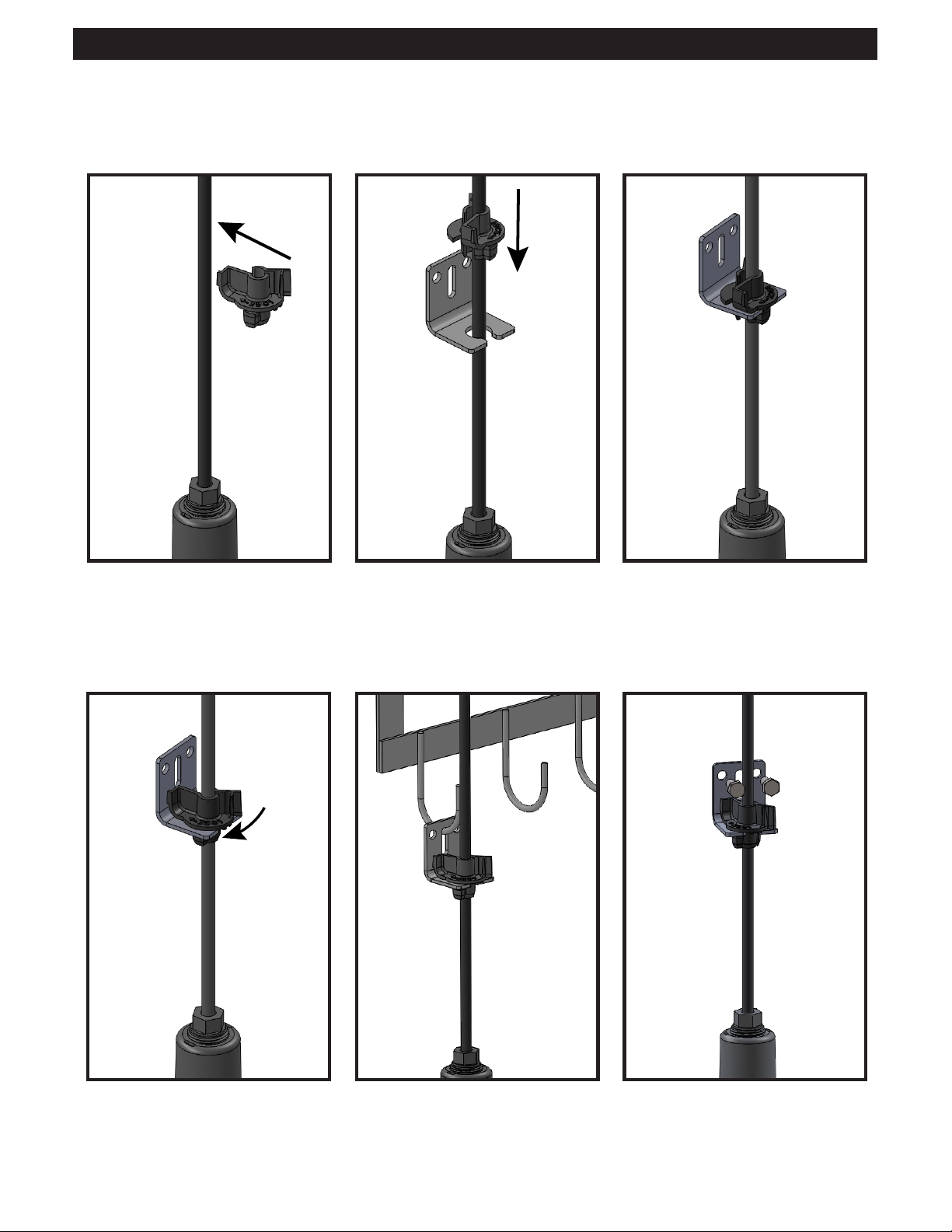
MOUNTING BRACKET
The PSLT Transmitter is supplied with a stainless steel mounting bracket and a strain relief cord grip.
90°
Step 1 Step 2 Step 3
Step 4 Step 5 (option 1) Step 5 (option 2)

3
ELECTRICAL CONNECTION
SHIELD: Connect to signal ground
(low impedance)
BLACK WIRE: +8 to 32 VDC
WHITE WIRE: 4 - 20 mA
VENT TUBE
1. Anchoring: Install the PSLT in a stilling well when possible, to prevent damage from impact. It is acceptable
to suspend the transmitter without a protective stilling well provided extra care is taken to prevent damage to the
transmitter and cable. Do not mount the transmitter to a pump or piping.
2. Submersion: Damage to the cable will lead to failure of the transmitter. The PSLT cable has a rugged jacket
material to minimize the risk of cuts and abrasions. Carefully lower your transmitter into the well, make sure the
cable does not contact sharp edges. Do not drop the transmitter.
3. Condensation Protection: The size of the vent tube is designed to minimize the intrusion of water vapor
when the cable is terminated inside a clean and dry control panel. In areas of high humidity, use a drying
tube (desiccant) or bellows to prevent water vapor from entering the vent tube. Contact Primex for ordering
information. Never terminate the transmitter cable in a junction box in the wet well.
4. Cable: The PSLT cable is exible; however, the vent tube inside the cable must not be kinked during
installation. Do not bend cable to a radius smaller than 1.5 inches (38 mm). If a liquid tight cord grip is used with
the transmitter cable, do not over tighten. This may cause damage to the cable and restrict the vent tube.
5. Mounting position: The PSLT must be installed in a vertical position with cable on top.
INSTALLATION
MAINTENANCE
• Periodically check the cable and housing for damage.
• Carefully remove excessive buildup on sensor.
• Periodically check the operation and output signal of the transmitter.
• Replace the product immediately if any damage is found or suspected.
• Use only PRIMEX replacement parts.
The PSLT is a loop transmitter (2-wire) designed to operate within a specific voltage range.

4
PUMP
CABLE
CONDUIT
SENSOR
CABLE
CONDUIT
IN-FLOW
DISCHARGE
BACK UP
FLOAT
HIGH LEVEL
BACK UP
FLOAT
LOW LEVEL
LEVEL
TRANSMITTER
WITH
STABILIZING
WEIGHT
PUMP
WARNING:
Keep oats and transmitter clear of pumps, pipes, and motor cables.
Ensure oats and transmitter cannot reach pump suction.
Do not run pump and level sensor cables in the same conduit.
TYPICAL LIFT STATION WITH TRANSMITTER AND FLOAT BACK UP

5
PART NUMBER DESCRIPTION DATE INSTALLED
1050714 PSLT 16.7ftWC with 50ft cable
1050713 PSLT 16.7ftWC with 75ft cable
1050712 PSLT 16.7ftWC with 100ft cable
1050717 PSLT 33.4ftWC with 50ft cable
1050716 PSLT 33.4ftWC with 75ft cable
1050715 PSLT 33.4ftWC with 100ft cable
*Backed by a 2-year limited warranty.
PSLT Analog Input Scaling Table
mA %TRANSMITTER 0-16.7FTWC TRANSMITTER 0-33.4FTWC
Ft (cm) In (mm) Ft (cm) In (mm)
20 100 16.7 (509) 200 (5,090) 33.4 (1,180) 400 (10,180)
16 75 12.5 (382) 150 (3,820) 25 (764) 300 (7,635)
12 50 8.4 (254) 100 (2,540) 17 (508) 200 (5,090)
8 25 4.2 (127) 50 (1,270) 8.5 (254) 100 (2,540)
40 0 (0) 0 (0) 0 (0) 0 (0)
844-4PRIMEX (477-4639)
WWW.PRIMEXCONTROLS.COM
© 2016 SJE-Rhombus®PN 1051390B
PRIMEX®is a trademark of SJE-Rhombus®
Viton® is a trademark of E. I. DuPont de Nemours and Company Corporation
SPECIFICATIONS
• Measuring Ranges: 7.25 PSI (16.7 ftWC) and 14.50 PSI (33.4 ftWC)
• Accuracy: 1% full scale
• Operating Temp: 32-122°F (0-50°C)
• Output: 4-20 mA, loop powered
• Excitation Voltage: 8-32 VDC reverse polarity protection
• Overpressure Protection: 58 PSI (133.6 ftWC)
• IP Rating: IP 68 for permanent submersion
• Wetted Materials:
• Sensor Housing: PVC, 2.00” diameter x 5.62” length (51mm x 143mm)
• Cable Seal: EPDM
• Diaphragm: VITON®, 1.25” diameter (32mm)
• Cable: TPE, 18 AWG - 2 wire shielded with vent tube, 0.3” diameter (8mm)
• Stabilizing Weight: Epoxy coated cast iron, 1.0 lb. (0.45 kg),
2.6” diameter x 2.5” length (66mm x 64mm)

INFORMACIÓN IMPORTANTE
• Aplicaciones: estaciones con bombas aspirantes de aguas residuales y euentes, estaciones de
bombeo de aguas pluviales, sistemas de agua no potable, tanques, pozos húmedos y depósitos.
• Primex® recomienda usar un ltro desecante o fuelles para proteger contra la entrada de humedad en
el tubo de venteo.
• No doblar el cable a un radio de curvatura inferior a 38 mm (1,5 pulgadas) para evitar que se tuerza el tubo
de venteo.
• Durante la instalación, bajar el transmisor lentamente y evitar el impacto con objetos al interior del
pozo húmedo.
• No presionar contra el diafragma del transmisor con objetos puntiagudos.
PESA ESTABILIZADORA
Cada PSLT trae una pesa estabilizadora desmontable. La pesa estabilizadora debe ir sujetada a la
carcasa del transmisor antes de la instalación. Es suciente con apretar usando la mano.
PELIGRO DE CHOQUE ELÉCTRICO
Desconecte el cable de alimentación antes de instalar este
producto o de hacerle mantenimiento. La instalación y el
mantenimiento de este producto deben ser efectuados por
personal idóneo siguiendo las normas aplicables en cuanto a
instalaciones eléctricas y plomería.
PELIGRO DE INCENDIO O EXPLOSIÓN
No utilice este producto con líquidos inama-
bles. No lo instale en lugares peligrosos deni-
dos como tales en el Código Eléctrico Nacional
de Estados Unidos, ANSI/NFPA 70.
De no tomarse estas precauciones, pueden ocasionarse lesiones serias o mortales. Remplazar este producto inmediatamente si el cable del
interruptor está dañado o partido. Este producto debe ser instalado siguiendo el Código Eléctrico Nacional de EE.UU., ANSI/NFPA 70, para evitar la
entrada o acumulación de humedad al interior de la caja del controlador.
TRANSMISORES DE NIVEL SUMERGIBLES
PRIMEX®(PSLT)
INSTRUCCIONES DE INSTALACIÓN
6
30° - 40°
Paso 1 Paso 2
Paso 3 Paso 4

7
SOPORTE DE MONTAJE
El transmisor PLST trae un soporte de montaje en acero inoxidable y un conector de alivio de tensión
para cables.
90°
Paso 1 Paso 2 Paso 3
Paso 4 Paso 5 (opción 1) Paso 5 (opción 2)

8
CONEXIÓN ELÉCTRICA
BLINDAJE: conectar a la terminal
de tierra de la señal (impedancia baja)
ALAMBRE NEGRO: +8 hasta 32 VCC
ALAMBRE BLANCO: 4 - 20 mA
TUBO DE VENTEO
1. Anclaje: en lo posible, instalar el PSLT dentro de un tubo tranquilizador (stilling well) para evitar daños
por impacto. Es apropiado suspender el transmisor sin el tubo tranquilizador de protección siempre y
cuando se tenga mucho cuidado a n de evitar daños al transmisor y al cable. No montar el transmisor en
bombas ni tuberías.
2. Inmersión: el daño del cable produce fallo del transmisor. El cable del PSLT viene cubierto con un
material resistente para minimizar el riesgo de cortes y abrasión. Bajar con cuidado el transmisor al
interior del pozo y comprobar que el cable no entre en contacto con bordes puntiagudos. No dejar caer el
transmisor.
3. Protección contra la condensación: el tamaño del tubo de venteo fue diseñado con el n de
minimizar la entrada de vapor de agua cuando el cable se termina al interior de un panel de control seco
y limpio. En áreas de alta humedad, usar un tubo de secado (desecante) o fuelles para evitar la entrada
de vapor de agua al tubo de venteo. Comunicarse con Primex para la información sobre órdenes de
pedido. Nunca se debe terminar el cable del transmisor en una caja de conexiones en el pozo húmedo.
4. Cable: el cable del PSLT es exible; sin embargo, el tubo de venteo al interior del cable no puede
estar doblado o torcido durante la instalación. No doblar el cable a un radio de curvatura inferior a
38 mm (1,5 pulgadas). Si se usa un conector hermético de alivio de tensión en el cable del transmisor, no
apretarlo demasiado. Esto podría ocasionar daños al cable y restringir el tubo de venteo.
5. Posición de montaje: el PSLT debe ser instalado en posición vertical con el cable en la parte superior.
INSTALACIÓN
MANTENIMIENTO
1. Revisar periódicamente que no haya daños al cable o a la carcasa.
2. Eliminar con cuidado la acumulación excesiva de desechos en el sensor.
3. Vericar periódicamente el funcionamiento y la señal de salida del transmisor.
4. Remplazar el producto inmediatamente si se sospechan o encuentran daños.
5. Usar exclusivamente piezas de repuesto de PRIMEX.
El PSLT es un transmisor de bucle (2 alambres) diseñado para operar dentro de un determinado rango
de voltaje.

9
CONDUCTO
DEL CABLE
DE LA BOMBA
CONDUCTO
DEL CABLE
DEL SENSOR
FLUJO DE ENTRADA
DESCARGA
FLOTADOR
DE RESPALDO
DE NIVEL ALTO
FLOTADOR
DE RESPALDO
DE NIVEL BAJO
TRANSMISOR
DE NIVEL
CON PESA
ESTABILIZADORA
BOMBA
ADVERTENCIA:
Los otadores y el transmisor deben estar alejados de bombas, tuberías y cables de motor.
Asegurarse de que los otadores y el transmisor no alcancen la succión de la bomba.
No operar la bomba ni los cables del sensor de nivel en el mismo conducto.
ESTACIÓN DE BOMBEO CARACTERÍSTICA CON TRANSMISOR Y
FLOTADOR DE RESPALDO

10
NÚMERO DE PARTE DESCRIPCIÓN FECHA DE INSTALACIÓN
1050714
PSLT 16,7ftWC con cable de 50 pies
1050713
PSLT 16,7ftWC con cable de 75 pies
1050712
PSLT 16,7ftWC con cable de 100 pies
1050717
PSLT 33,4ftWC con cable de 50 pies
1050716
PSLT 33,4ftWC con cable de 75 pies
1050715
PSLT 33,4ftWC con cable de 100 pies
*Respaldado con garantía limitada de 2 años.
**ftWC = pies de columnma de agua
Tabla de escalas de entradas analógicas del PSLT
mA %TRANSMISOR 0-16,7FTWC TRANSMISOR 0-33,4FTWC
pies (cm) pulgadas (mm) pies (cm) pulgadas (mm)
20 100 16,7 (509) 200 (5.090) 33,4 (1.180) 400 (10.180)
16 75 12,5 (382) 150 (3.820) 25 (764) 300 (7.635)
12 50 8,4 (254) 100 (2.540) 17 (508) 200 (5.090)
8 25 4,2 (127) 50 (1.270) 8,5 (254) 100 (2.540)
40 0 (0) 0 (0) 0 (0) 0 (0)
+1-844-4PRIMEX (477-4639)
WWW.PRIMEXCONTROLS.COM
© 2016 SJE-Rhombus®PN 1051390B
PRIMEX®es una marca registrada de SJE-Rhombus®
Viton® es una marca registrada de E. I. DuPont de Nemours and Company Corporation
ESPECIFICACIONES
• Rangos de medición: 7,5 PSI (16,7 ftWC) y 14,0 PSI (33,4 ftWC)
• Precisión: 1% de la escala completa
• Temperatura de operación: 0-50 °C (32-122 °F)
• Salida: 4-20 mA, alimentación por bucle
• Tensión de excitación: 8-32 VCC y protección contra inversión de la polaridad
• Protección contra sobrepresión: 58 PSI (133,6 ftWC)
• Grado de protección IP: IP 68 para inmersión permanente
• Materiales en contacto con el agua:
• Carcasa del sensor: PVC, 51 mm de diámetro x 143 mm de longitud (2,00” x 5,62”)
• Sello del cable: EPDM
• Diafragma: VITON®, diámetro de 32 mm (1,25”)
• Cable: TPE, 18 AWG - 2 alambres blindados con tubo de venteo, diámetro de 8 mm (0,3”)
• Pesa estabilizadora: hierro fundido con recubrimiento epóxico, 0,45 kg (1,0 lb)
66 mm de diámetro x 64 mm de longitud (2,6” x 2,5”)
Tabla de contenidos
Idiomas:
Otros manuales de Transmisor de Primex

Primex
Primex XR Manual de usuario

Primex
Primex 14000 Series Manual de operación

Primex
Primex UK SATELLITE TRANSMITTER Manual de operación

Primex
Primex XR 5 Watt Hoja de instrucciones

Primex
Primex XR TIME SYNCHRONIZATION Manual de operación

Primex
Primex XR PERSONAL SERIES Manual de usuario

Primex
Primex XR PERSONAL SERIES Manual de usuario

Primex
Primex XR Manual de usuario
Manuales populares de Transmisor de otras marcas


Dejero
Dejero EnGo 3x Manual de usuario

Rosemount
Rosemount 4600 Manual de usuario

Speaka Professional
Speaka Professional 2342740 Manual de usuario

trubomat
trubomat GAB 1000 Manual de usuario

Teledyne Analytical Instruments
Teledyne Analytical Instruments LXT-380 Manual de usuario

Rondish
Rondish UT-11 Manual de usuario


