Presto Lifts M100 Manual

Foot Operated Lifts
M100, M200,
M300 & M400
Installation, Operation
and Service Manual
Model Number ___________________
Serial # _________________________
Date placed in service _____________
IMPORTANT: READ CAREFULLY
BEFORE INSTALLING OR OPERATING LIFT
Part orders are subject to a $50 miminum charge.
April 2007

OWNER’S MANUAL Page 2 M100, M200, M300 & M400 FOOT OPERATED LIFTS
This manual was current at the time of printing. To obtain
the latest, most updated version, please contact Presto Lifts
Customer Service Department or go to our website:
www.PrestoLifts.com -- you will find a complete list of
current owner’s manuals to print.

OWNER’S MANUAL Page 3 M100, M200, M300 & M400 FOOT OPERATED LIFTS
C O N T E N T S
S E C T I O N 1:
Introduction ........................................................................................................... 4
S E C T I O N 2:
Safety ..................................................................................................................... 4
S E C T I O N 3:
Installation ............................................................................................................. 4
S E C T I O N 4:
Operation ............................................................................................................... 4
S E C T I O N 5:
Maintenance........................................................................................................... 5
S E C T I O N 6:
Service ................................................................................................................... 6
S E C T I O N 7:
Troubleshooting..................................................................................................... 6
RESTOCKING POLICY................................................................................................. 18
RETURN GOODS AUTHORIZATION (RMA) PROCEDURES ................................. 19
ORDERING REPLACEMENT PARTS.......................................................................... 20
WARRANTY .............................................................................................BACK COVER
L I S T O F F I G U R E S :
Table 1: Hydraulic Oil Specifications ............................................................................................ 5
Figure 1: Wheel Identification..........................................................................................................7
Figure 2: Chain RollerAssembly .....................................................................................................7
Complete Cylinder breakdown by Part Number (Text) .............................................................. 8-9
Figure 3: M100-10 Pump Body Complete.....................................................................................10
Figure 4: M400-20 CylinderAssembly Repair Kit ........................................................................ 11
Figure 5: M400-30 Pump PlungerAssembly.................................................................................12
Figure 6: M400-40 Cylinder Packing Kit.......................................................................................13
Figure 7: M400-50 Release PinAssembly ....................................................................................14
Figure 8: BackplateAssembly .......................................................................................................15
Figure 9: PlatformAssembly .........................................................................................................16
Figure 10: StackerAssembly .........................................................................................................17

OWNER’S MANUAL Page 4 M100, M200, M300 & M400 FOOT OPERATED LIFTS
• Do not put hands or feet on or near the mast
while the forks or platform is in motion.
• Do not stand, sit or climb on the lift.
• Do not exceed the load capacity.
• Place all loads centrally located on the lift forks or
platform.
• Do not place a load on a moving lift.
• Do not use the lift on soft, uneven or unstable
surfaces.
• Do not shock load the forks or platform. Materi-
als must be carefully placed rather than dropped.
S E C T I O N 3
INSTALLATION
INSTALLATION
When the stacker arrives on a pallet the following steps
are to be followed:
1. Through the use of a forklift or overhead hoist, pick
the stacker unit up taking into consideration the center
of gravity. The center of gravity of the unit should be
adequately supported.
2. Once the unit is lifted from the pallet by a couple of
inches, remove the pallet from under the stacker.
3. Follow the next sections to ensure proper operation.
S E C T I O N 4
OPERATION
METHOD OF OPERATION:
In order to operate the lift follow these operating pro-
cedures.
1). To raise the platform or forks, pump foot pedal un-
til platform reaches desired height.
2). To lower lift, press release pedal down. Pressure on
release pedal controls speed of descent of load.
S E C T I O N 1
INTRODUCTION
This manual attempts to provide all of the information
necessary for the safe and proper installation, opera-
tion and maintenance of Presto Lifts Inc.'s MSeries
Stackers. It is important that all personnel involved
with the installation, maintenance or operation of the
stackerread thismanual. Where uniquesituations arise,
that are not covered in this manual call Presto Lifts for
further instructions. Additional manuals are available
upon request or on our web site at www.prestolifts.com.
The stacker has a nameplate that provides the load ca-
pacity ratings, serial number and model identifications.
Please refer to these numbers when ordering parts or
requesting further information.
WHERE UNIQUE SITUATIONSARISE, THATARE
NOTCOVERED INTHISMANUAL, CALLPRESTO
LIFTSSERVICEDEPARTMENTFOR FURTHERIN-
STRUCTIONS.
S E C T I O N 2
SAFETY
The M Series stackers are very capable of causing seri-
ous injury or damage if adequate precautions are not
taken. By reading and following this manual, operator
injury may be prevented.
DO NOT INSTALL OR OPERATE THESE LIFTS
WITHOUT CAREFULLY READING THIS
MANUAL. In order to provide for the safe operation
of these stackers, Presto Lifts Inc. has identified certain
hazards that may occur during the installation, mainte-
nance and use of these lifts.
WARNING!
• Do not perform any repair work on lifts if there is
a load on the platform or forks are in the raised or
loweredposition.
• All personnel must stand clear of the lift when the
liftis inmotion.
• Do not put hands or feet under forks or platform
whilein motion.

OWNER’S MANUAL Page 5 M100, M200, M300 & M400 FOOT OPERATED LIFTS
S E C T I O N 5
MAINTENANCE
ROUTINE MAINTENANCE:
1). Grease wheels and casters at least once a month to maintain easy roll of lift.
2). Do not overload the lift. All foot operated Presto Manual Stackers have a maximum rated capacity
of 1000 lbs.
3). Use only hydraulic oil in the hydraulic system. NEVER USE HYDRAULIC BRAKE FLUID.
Table 1 – Hydraulic Oil Specifications
If the lift will be used at normal ambient temperatures, Presto Lifts supplies the unit with
CitgoAW 32 oil. This may be replaced by any other good quality oil with 150 SSU at 100°
F and rust and oxidation inhibitors and anti-wear properties.
If the lift will be used at ambient temperatures below 0°F, use aircraft hydraulic oil. Use
Type 15 aircraft hydraulic oil.
The following are equivalent to CITGO AW32:
TYPE MANUFACTURER
DTE 24 ............................. EXXON/MOBIL
NUTO H32........................ EXXON/MOBIL
AMOCO AW32.................. CHEVRON (AMOCO CO.)
CAUTION!
It is very important to keep the hydraulic oil free of dirt, dust, metal chips,
water, and other contamination. Most of the problems with hydraulic systems
are caused by contamination in the oil.

OWNER’S MANUAL Page 6 M100, M200, M300 & M400 FOOT OPERATED LIFTS
S E C T I O N 7
TROUBLESHOOTING
If lift does not rise to full height:
It probably requires oil. (Check with lift in down
position.) To fill cylinder with oil, follow these in-
structions.
There are two pipe plugs in the cylinder, Part No.
M427 (Vent Plug) and part No. M428 (Oil Level
Plug). Remove both plugs.
Put a good grade of hydraulic jack oil in the cylin-
der through the top hole. When the oil reaches the
level of the bottom hole, replace both plugs. TOP
PLUG IS A BREATHER PLUG, BE SURE TO
REPLACEPLUGSIN THEIR PROPERPLACES.
If lift does not hold load, or tends to drift down-
ward under a load:
Dirt particle may be obstructing seating of the
valve, allowing leakage.
Ifdirtparticleis obstructing seatingofthevalve:
Open release valve by pressing down on release
pedal. At the same time, pump foot lever three or
fourstrokes.Dothisthreeorfourtimes.Thenplace
some weight on the platform or forks and pump
foot lever until platform reaches its full height.
Now, lower lift six inches to a foot at a time. This
should dislodge dirt and lift should work properly.
S E C T I O N 6
SERVICE
To remove cylinder from lift:
1. Pump lift to above 12'' height and then prop plat-
form or forks up to keep it in raised position.
2. Step on release pedal and push ram down by
hand until it reaches its lowest point.
3. Slip chain off pulley and remove pulley assem-
bly.
4. Take off two bottom cap screws that hold cylin-
der in place and slide cylinder forward towards the
base legs of the lift. The cylinder can now easily
be removed.
To replace ram chevron set in hydraulic cylin-
der assembly:
1. Remove hydraulic cylinder from lift and remove
VentPlug(PartNo.M427)and Oil Level Plug (Part
No. 428) and drain oil from cylinder.
2. Clamp pump body in vise, unscrew top hex nut
and remove outer cylinder.
3. Remove inner cylinder from pump making sure
not to distort or mar cylinder. Note: Do not use
pipe wrench.
4.Removeram and replace chevronset.
5.Pushram intoinnercylinder --chevronend last!
6.Reassembleandfillwithcleanhydraulicjackoil.
OWNER’S MANUAL Page 7 M100, M200, M300 & M400 FOOT OPERATED LIFTS
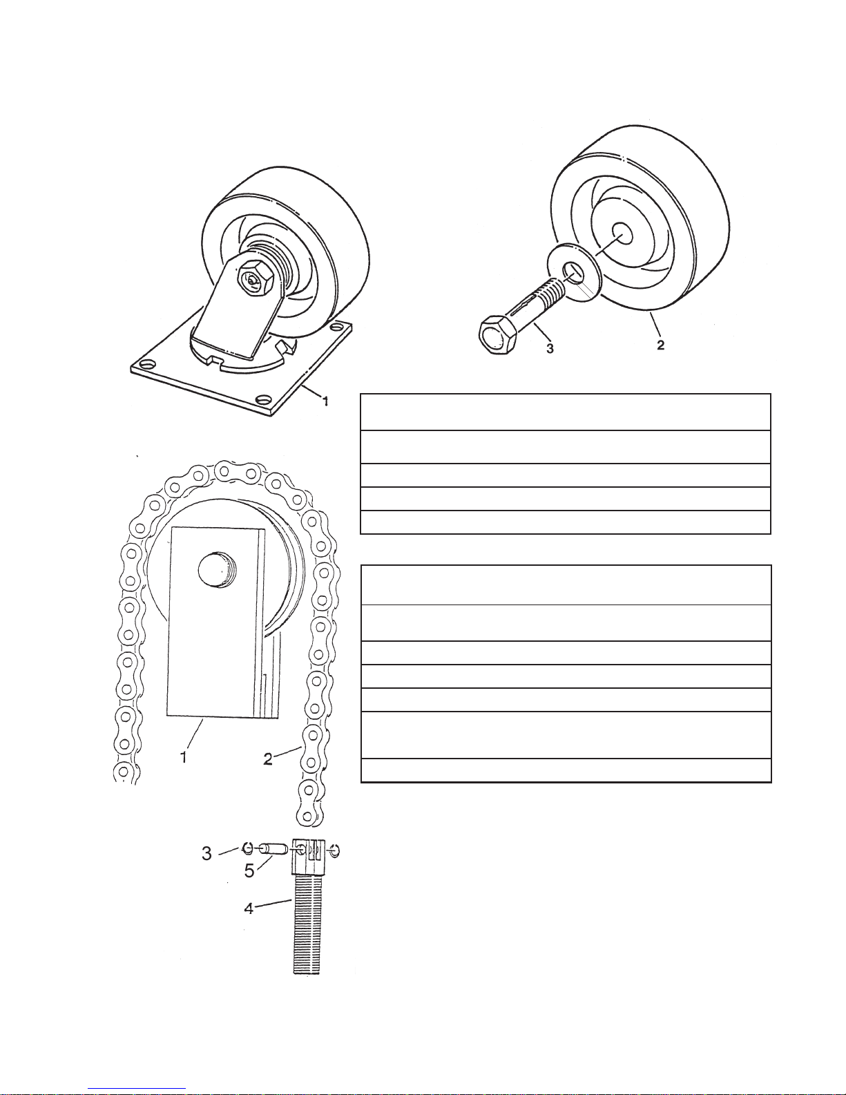
F I G U R E 2:
CHAIN
ROLLER
ASSEMBLY
F I G U R E 1:
WHEEL IDENTIFICATION
WHEELIDENTIFICATION
ITEM NO. PART NUMBER DESCRIPTION
1 C101PH2 Swivel Caster Assembly
2 C102PH Rigid Phenolic Wheel
3 C103 Mounting Hardware
** SPECIFIC MODEL NUMBER
REQUIRED WHEN ORDERING
FOR CORRECT CHAIN LENGTH
CHAINROLLERASSEMBLY
ITEM NO. PART NUMBER DESCRIPTION
1 0584-VR Single Chain Assembly
2 C104** Chain
3 C106B Lock Ring
4 C106C Chain Socket
3/4'' Adjustable
5 C106A Clevis Pin

OWNER’S MANUAL Page 8 M100, M200, M300 & M400 FOOT OPERATED LIFTS
R E C O M M E N D E D C Y L I N D E R S P A R E P A R T S L I S T I N G
M SERIES STACKERS - PAGE 1
PART # DESCRIPTION AVAILABILITY KIT#
M400** Hydrualic Cylinder Assy. Complete
M402 Release Lever A
M403 Release Lever Pin A
M404 Pump Plunger Clip A
M407 N/A see 0457 K
M410 Pump Body K 1 & 2
N1200 Pump Body Plug A 1 & 2
M412 Pump Check Ball K 1 & 2
M413 Pump Check Spring K 1 & 2
M414 Pump Valve/Release Gaket A 1 & 2
M415 Pump Valve Bolt K 1 & 2
M416 Release Ball & Poppet K 1 & 2
M417 Release Spring K 1 & 2
M419 Release Bolt K 1 & 2
M420 O Ring Reservoir Seal K 4 & 2
M422 Pump Lever Bracket A
M423 Pump Lever Bracket Pins A
M424 Ram O Ring Seal K 4 & 2
M425 CylinderNut A
M426** Outer Cylinder N
M427 Vent Plug A
N1200 Oil Lever Plug A
M429 Pump Lever Return Spring A
M430** Inner Cylinder N
M431** Ram N
M432 Ram Guide Bearing Plate K 4 & 2
M433-01 Ram Chevron Set A 4 & 2
M434 Ram Chevron Set Washer K 4 & 2

OWNER’S MANUAL Page 9 M100, M200, M300 & M400 FOOT OPERATED LIFTS
R E C O M M E N D E D S P A R E P A R T S L I S T I N G
M SERIES STACKERS - PAGE 2
PART # DESCRIPTION AVAILABILITY KIT#
M435 Ram Cup Nut K 4 & 2
M436 Foot Lever A
M437 Foot Lever Pad A
M438 Pump Intake Spring K 1 & 2
M439 Pump Intake Ball A 1 & 2
M440 Release Pin O Ring K 5 & 2
M441 Release Pin Back-Up Ring K 5 & 2
M442 Release Pin K 5 & 2
M443 Plunger Sleeve Gasket A 1-3 & 2
M444 Plunger Sleeve K 1-3 & 2
M445 Plunger O Ring A 1-3 & 2
M446 Plunger Nut A 1-3 & 2
M447 Plunger Washer A 1-3 & 2
M448 Plunger Cup A 1-3 & 2
N0040 Nut A
N0810 Bolt A
0457 Square Pump Plunger K 1-3 & 2
** SPECIFIC MODEL NUMBER REQUIRED
NOTE: A = AVAILABLE
N = NOTAVAILABLE; Must buy complete Cylinder
K = In a kit only.
Kit Number: 1 = M400-10
Kit Number: 2 = M400-20
Kit Number: 3 = M400-30
Kit Number: 4 = M400-40
Kit Number 5 = M400-50
OWNER’S MANUAL Page 10 M100, M200, M300 & M400 FOOT OPERATED LIFTS
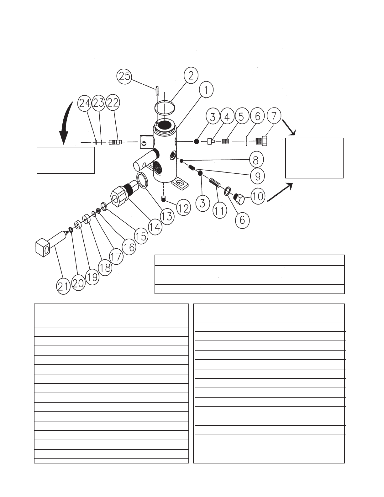
F I G U R E 3: M400-10 PUMP BODY COMPLETE
ITEM PART QTY DESCRIPTION
NO. NO.
1 M410 1 Pump Body
2 M420 1 Reservoir Seal O Ring
3 M412 2 Pump Check Ball
4 M416A 1 Poppet
5 M417 1 Release Spring
6 M414 2 Gasket
7 M419 1 Release Bolt
8 M439 1 Pump Intake Ball
9 M438 1 Pump Intake Spring
10 M415 1 Pump Valve Bolt
11 M413 1 Pump Check Spring
12 M411 1 Plug
13 M443 1 Gasket
14 M444 1 Plunger Sleeve
ITEM PART QTY DESCRIPTION
NO. NO.
15 M445 1 Plunger O Ring
16 M446 1 Plunger Nut
17 M447 1 Washer
18 M448 1 Plunger Cup
19 M407A 1 Plunger Guide Brg.
20 M407B 1 Seal O Ring
21 0457 1 Pump Plunger
22 M442 1 Release Pin
23 M440 1 Release Pin O Ring
24 M441 1 Release Pin
Back Up Ring (Split)
25 M410-D 1 Pin, Spring Roll
P/N M400-10 Pump Body Complete includes all items below.
P/N M400-30 Pump Plunger Assembly includes items 13 thru 21.
P/N M400-50 Release Pin Assembly includes items 22 thru 24.
See pages 7 & 8 for availability of individual items.
Tip: Donotswap
#7 & #10.
Theyaremachined
differently
Tip: Removalof
#22, #23, & #24
through#7 portal
Otros manuales para M100
1
Este manual sirve para los siguientes modelos
3
Tabla de contenidos
Manuales populares de Ayuda a la movilidad de otras marcas


Rhythm Healthcare
Rhythm Healthcare B3800F Manual de usuario

AMF-BRUNS
AMF-BRUNS PROTEKTOR Manual de usuario

Drive DeVilbiss Healthcare
Drive DeVilbiss Healthcare OTTER Manual de usuario

Rhythm Healthcare
Rhythm Healthcare C500U Manual de usuario

Lumex
Lumex RJ4200A Manual de usuario

Rebotec
Rebotec Jumbo Manual de usuario