
Precision Power PMQ-210 Manual de usuario

CONTENTS
(click on a topic to view)
Congratulations SystemTuning
Features and Specifications SystemTuning
Detachable Control Panel Frequency Distribution
Installation / Mounting System 1
Wiring System 2
Wiring Troubleshooting
Functions Block Diagram
Parametric Operation Control Panel
SystemTuning Warranty
PMQ 210 Ten Band Parametric Equalizer OWNERS MANUAL POWER CLASS
TM

Caution!
The extended use of a high powered audio system may
result in hearing loss or damage. While
PrecisionPower
systems are capable of
"Concert Level"
volumes with
incredible accuracy, they are also designed for you to
enjoy at more reasonable levels all of the sonic subtleties
created by musicians. Please observe all local sound
ordinances.
for choosing
PrecisionPower
audio epuipment. At
PrecisionPower
we
proudly design, engineer and manufacture audio products at our facility in
Phoenix, Arizona. Our award winning engineering team utilizes innovative
technology to consistently deliverAbsolutely State of theArtTM performance,
sound quality, reliability, and value. This
PrecisionPower
product reflects
our commitment to offer you unparalleled versatility and quality for years of
dependable service and listening enjoyment.
Service
Do not attempt to service
PrecisionPower
products yourself.
Performing exploratory surgery on your audio equipment yourself
will void the warranty. Many parts of your
PrecisionPower
gear
are custom built to our specifications. Our factory parts are not
made available to anyone else nor are they for sale. Our goal
is to make sure that your
PrecisionPower
product will always
sound as good as the day it was purchased. Contact your
authorized
PrecisionPower
dealer about obtaining any warranty
service through
PrecisionPower
.(See Warranty insde back cover)
FOR YOUR RECORDS:
Model
Serial Number
Purchase Date
Congratulations and thank you.....
BACKTO CONTENTS

10 Band Fully Parametric Equalizer
Detachable control panel with 20 ft. cable
for remote adjustment
10 center detent adjustable gain controls
10 center detent adjustable Q controls
10 adjustable frequency controls
Differential input stage
Mono/Stereo switch
Attenuation Switch
Defeat switch
Gold RCA input and output connectors
PWM Power Supply
L.E.D. power indicator
Designed and Handcrafted in the U.S.A.
Specifications
Signal-to-Noise Ratio >102 dB
Total Harmonic Distortion
(1kHz, 1VRMS) 0.017%
Cut / Boost Range
±
12 dB
Input Gain 0 dB
Q Range 1.5 - 4
Attenuation -12 dB
Maximum Input Voltage
(attenuation out) 8 VRMS
Maximum Input Voltage
(attenuation in) 16 VRMS
Maximum Output (10 k
Ω
Load) 8 VRMS
Frequency Response 0 to 50kHz
±
1dB
Supply Voltage 11-15 VDC
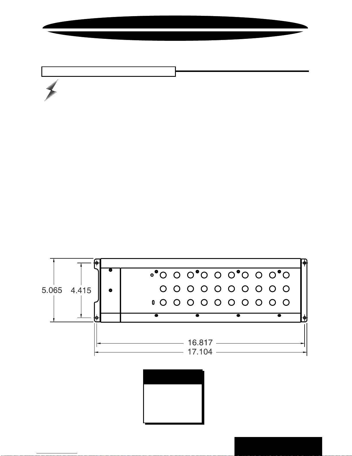
Dimensions 17.10" L
5.065" W
1.783" H
FEATURES / SPECIFICATIONS
1BACKTO CONTENTS

Using the Two Part Design to your Advantage
2
In the past, when adjusting the system equalizer, it was necessary to
gofromthetrunktotheRTAoutside of the vehicle, or to the passenger
compartment to listen to the changes made. Equalizing a system by
going back and forth in this manner is a time consuming, difficult
process. With the
PMQ-210
this is no longer the case. Before you
begin your equalization process, simply remove theAllen head screw
(located to the right of the thumb notch on the front bezel) that holds
the main control panel to the docking bay, and carefully remove the
main control panel. You will notice that it is connected to the docking
bay via a short eight conductor cable. Make sure that the power is off!
Remove the control panel, disconnect the short cord at both ends
and then replace it with the 20 ft. cable (supplied).After plugging the
control panel into the docking bay, turn power back on, and begin
your pink noise analysis. This feature allows you to instantly make
"real time" adjustments to the system.
DETACHABLE CONTROL PANEL
BACKTO CONTENTS
3
Mounting
To prevent damage to the equalizer while driving, mount it in a
secure place. Choosing the appropriate location will depend
upon your vehicle and the complexity of your system design.
Typical mounting locations include the trunk and passenger
compartment(floororunderseat).Duetothe potential of noise
interference,wedonotrecommendmountingthecontrol panel
away from the main chassis of the
PMQ-210
. Never mount the
equalizer in a location that would subject it to immersion or
exposure to water.
Once a location has been chosen, securely mount the
PMQ-210
with four mounting screws. Be Careful! Inspect the
areaunderneathtobesureyouarenotdrillingintowires,brake
or fuel lines, that could be damaged by the drill bit or screws.
INSTALLATION / MOUNTING
Dimensions
5.065"W
17.10" L
1.783"H
BACKTO CONTENTS

4
WIRING
eject
VOLUME
BASS TREBLE
RIGHT
LEFT
BALANCE TRACK
REVERSE
FOWARD
1234
876
5
PPI MAR KET ING DPT
Trk1
Before beginning, disconnect the negative (-) terminal of the
battery prior to working on the positive (+) terminal to prevent
a short to ground. This is important, unless you want to spend
the rest of your life with a nickname like
"Sparky,"
or
"Smokey."
Reconnectthenegative terminalonlyafterallconnectionshave
been made.
NOTE
BACKTO CONTENTS
5
The next step is to connect the Power, Ground, and Remote wires to
your
PMQ-210
.The power wireshouldrunfromthemountinglocation
through the vehicle to the battery or power distribution block. Avoid
sharpcorners, creases, and sharp bodyparts.When passing through
any metal wall (i.e. firewall etc.), a grommet must be used to prevent
the wire from chaffing and shorting to ground.
The ground wire should be of the same gauge as the power wire. As
a rule of thumb, use as short a length of wire as possible.
Find a location near the equalizer that is metal (the floor is ideal) and
clean an area about the size of a quarter to bare metal. Drill a pilot
holeinthemiddleofthisarea. BeCareful! Inspecttheareaunderneath
to be sure you are not drilling into wires, brake or fuel lines, etc.
Terminate the wire with a ring connector and attach it to the bare
metal using a #8 sheet metal screw and washer (not supplied). We
suggestcrimping and/orsolderingthisconnection.Aftertheconnection
is complete, coat the area with silicone or some similar material to
prevent rust from developing.
Finally, the remote wire needs to
run to the power antenna (or
amplifierremote) lead of the head
unit. This wire supplies a 12 volt
signal to the
PMQ-210
when the
main system is activated.
Once you have routed the power,
ground,andremotewiresthrough
the vehicle, it is time to connect the wires to the
PMQ-210
. Be sure
that you have not reconnected the ground cable to the negative post
of the battery.
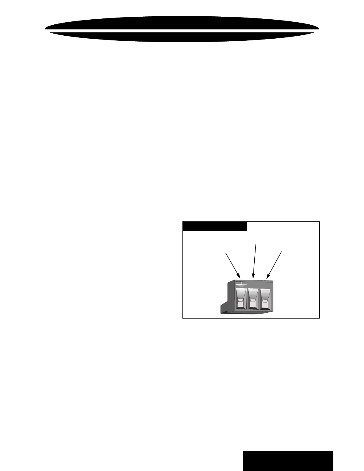
Cut off excess wire and, using wire strippers, strip the power, ground
and remote cables about 1/8 inch. Locate the power, ground, and
remote
Powerlock
connector (supplied). On the top of the connector
are three slotted screws. With a small flat-bladed screwdriver, loosen
the screws before attempting to insert the cables. After you have
inserted the stripped end of each cable into the connector, secure it
by tightening the associated screw. Check that each connection is
tight. If the wires are secure, the connector may be plugged into the
PMQ-210
.
WIRING
Remote
Ground Powe
r
T/O B+
Powerlock
BACKTO CONTENTS

6
FUNCTIONS
To useSpeakerLevelInputs (common ground headunitsonly),
connect RCA plugs to the front or rear speaker leads as shown,
and push IN the Attenuation switch.
WARNING:
If you are using a source unit with bridged high powered (or "floating
ground") speaker outputs, a suitable high to low level adapter must be used.If you
are unsure about your head unit see your local PrecisionPower dealer or call
1-800-62POWER
.
INPUT
- Connect RCA cables from your source unit here.
Attenuation
- Push this switch in to accept high level RCA inputs
or direct speaker lead inputs from common grounded
(not high powered) head units. See diagram below for wiring.
Stereo/Mono Switch - Push this switch IN to send Left Input to
both channels of the
PMQ-210
for Mono operation. Leave the
switch OUT for Stereo operation.
OUTPUT
- Connect RCA cables to your Preamp, Crossover or
Amplifier here.
After connecting Ground, Remote, and Power wires, plug in the
Powerlock
connector here.
BACKTO CONTENTS

7
PARAMETRIC OPERATION
The
PMQ-210
Parametric Equalizer puts an incredible amount of
control in your hands. Correctly adjusted, it can solve many of the
problems you will encounter along your road to perfect sound.
Incorrectlyadjusted, it can cause justasmany problems. By following
these guidelines, you will avoid common pitfalls in system tuning and
get your sound quickly dialed in. We recommend that you use a Real
TimeAnalyzer (RTA) to speed things up, but it is possible to tune your
system without it.
It is important to understand what a parametric equalizer actually
controlstobeable touseoneeffectively.Onthefaceof the detachable
control panel are ten sets of three controls each. On the top row are
the frequency selection controls, which allow you to dial in the exact
frequencies in need of adjustment. There are ten overlapping ranges
that cover the entire audio spectrum. The second row consists of the
"Q" adjustment from 1.5 to 4 for each frequency selected. Q is an
indication of how wide or narrow the adjusted bandwidth is. A low Q
(1.5)willaffectawiderangeoffrequenciesaroundtheselectedcenter
frequencyresultinginagentlycurvedshape,while a high Q (4) affects
a narrow band resulting in a peaked shape as shown below. The last
rowof controls determines the amountofcut or boost, ±12dB, ateach
selected frequency.
BACKTO CONTENTS

8
SYSTEM TUNING
1) With the system turned OFF, remove the control panel from the
chassis of the
PMQ-210
, replace the short connecting cable with
the 20' cable, and take the control panel to the adjusting location
(either inside the car or next to the RTA).
NOTE:If you are using a Real Time Analyzer (RTA), go to step 2.
If not, go to step 10.
2) The next step is to locate a suitable source of “pink noise." A
good choice would be the current IASCA competition reference
disc. Also, some RTAs have a built-in pink noise source. Ideally,
the pink noise should play through your head unit, allowing you to
compensate for any frequency response changes caused by it, or
anything else, before the amplifiers.
3) Next, place the microphone from the RTAin the driver's seat at
approximately head level. Initially, set the analyzer to read at 3dB
per step, and set the speed of the RTA’s readout to medium."Turn
onyour system andstartthe pink noise.Raise or lower thevolume
until you can see all (or most) of your frequency response on the
RTA scale (a little above or below is OK). Make sure all of the
equalizer's Cut/Boost controls are at zero and look at the RTA
screen.
4) You are trying to achieve a target frequency response, or "curve"
thatreflects yourpreference.Youmightthinkthataperfectlystraight
line would be best, but it really doesn't sound very good. Instead,
shoot for a curve that starts about 9dB up at the low frequencies
(25Hztoabout100Hz)droppinggentlyto0dBinthemidrange(250Hz
to 3kHz), then dropping gently to -9dB at 16kHz and 20kHz.
See the figure at the top of the next page.
5) If electronic crossovers are used, any large frequency sections
corresponding to your crossover points that are low or high should
be brought in line using crossover level controls or amp gain
adjustments rather than the equalizer.
BACKTO CONTENTS
Tabla de contenidos
Otros manuales de Ecualizador estéreo de Precision Power

Precision Power
Precision Power PAR-224 Manual de usuario

Precision Power
Precision Power PAR-225 Manual de usuario

Precision Power
Precision Power PAR-245 Manual de usuario

Precision Power
Precision Power PRECISIONPOWER DEQ-230 Manual de usuario

Precision Power
Precision Power E.DZ Manual de programación

Precision Power
Precision Power PAR-650 Manual de usuario

Precision Power
Precision Power PEQ-114 Manual de usuario

Precision Power
Precision Power PAR-224 Manual de usuario


