Precision Governors, LLC
1715 Northrock Ct
Rockford, IL 61103
Ph: 815-229-5300 Fax: 815-229-5342
www.pgcontrols.com
PG ENGINEERED CONTROL SOLUTIONS
ENGINEERED CONTROL SOLUTIONS
For 4 cylinder DISTRIBUTOR-LESS engines, set DIP switches 1-7 OFF.
For 4 cylinder DISTRIBUTOR engines, set DIP switch 1 ON and switches 2-7 OFF.
For 6 cylinder DISTRIBUTOR engines, set DIP switch 2 ON and switches 1 and 3-7 OFF.
For 8 cylinder DISTRIBUTOR engines, set DIP switch 1 and 2 ON and switches 3-7 OFF.
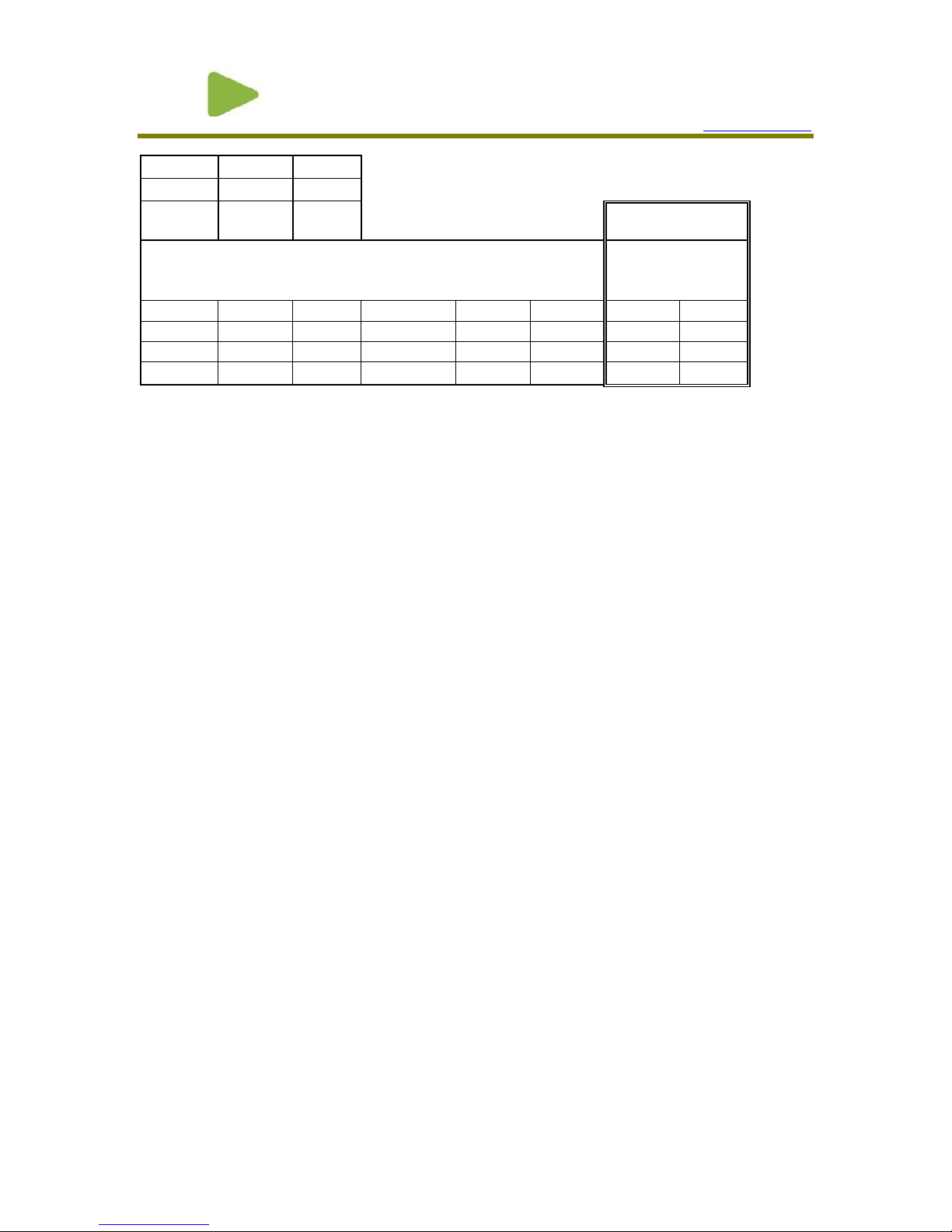
For other speed inputs, refer to the speed range adjustment in Figure 5.The controller needs to
know the speed pickup frequency to engine speed ratio to obtain the correct speed range. Diesel
engines typically have between 90 and 130 flywheel teeth ( Pulses / Rev). If in doubt, select a lower
pulse per rev setting and change to a higher setting if engine speed cannot be adjusted high enough.
The mag pickup frequency can be measured and compared to the high and low limits in the table.
CHECK-OUT &INITIAL START-UP PROCEDURES
As machines have different speed settings and wiring differs between machines, consult machine
service manuals for machine specific wiring, speed settings, and methods to command each set
speed. Precision Governors does not have information as to how particular machines are configured,
wired, or the proper speed settings.
Assuming that the Governor Assembly and Controller are mounted and the wiring is run and checked,
proceed as follows:
1) Set DIP switch to the desired governing mode and proper pulse per Rev count.
2) Turn ignition switch on. Do not start engine. The throttle actuator should not be powered when
the engine is NOT running.
3) Use a Multimeter to check battery voltage at battery terminals, and record. Now check voltage at
the machine connection points for terminals 1 & 2 ( 1 is +, 2 is - ).This voltage reading should be
the same as at battery. If not, shut down, and correct wiring.
4) Before proceeding, familiarize yourself with the locations of the Speed adjustment pots and the
Gain, Integral, and Derivative Pots, see Figure 5. Read the section on Adjustments.
5) Start engine then set machine controls as necessary to adjust all applicable set speeds. If engine
speed surges or is not stable, reduce Gain and / or adjust integral and derivative as needed.
6) Re-check voltage between the connections for terminals A & B as in step 2. Voltage reading
should be between 13.5--14.6 VDC. If less, look for undersized wiring somewhere in the system,
or for other components wired in parallel with the Governor.
7) Carefully adjust Gain. You are looking for the best compromise between quick response and
good stability. Make very small adjustments, then load and unload engine. Usually, a good set-up
is one that makes 1 to 3 small bounces and then steadies down after a large load change. Too
much Gain shows up as a rapid (once per second) instability, most commonly at light loads. Too
little Gain shows up in large over-shoots on start-up or large load changes, and generally sluggish
operation. A good initial setting for the gain is to turn fully counterclockwise and then turn
clockwise 3/8 of a turn. Changing the gain may affect the set speed.
8) Integral Adjustment. This adjustment is typically not critical for most applications. A good initial
setting for the integral is to turn fully counterclockwise and then turn clockwise 1/2 of a turn. This
adjustment affects how long the controller takes to completely recover from a load change. If,
after applying a load, the engine recovers below set speed then creeps up to the set speed over