HRX-C-HB-3 VIALITEHD C-BAND LINK HANDBOOK
3
TABLE OF CONTENTS
1INTRODUCTION.............................................................................................................................5
1.1 The C-Band............................................................................................................................................ 5
1.2 Typical deployment ................................................................................................................................ 5
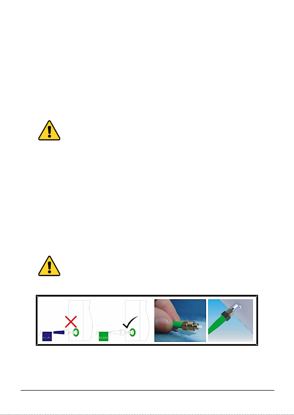
1.3 Care of fibre optic connectors................................................................................................................ 5
2SETTING UP AND UNDERSTANDING THE FIBRE OPTIC LINK.................................................6
2.1 Module operation ................................................................................................................................... 6
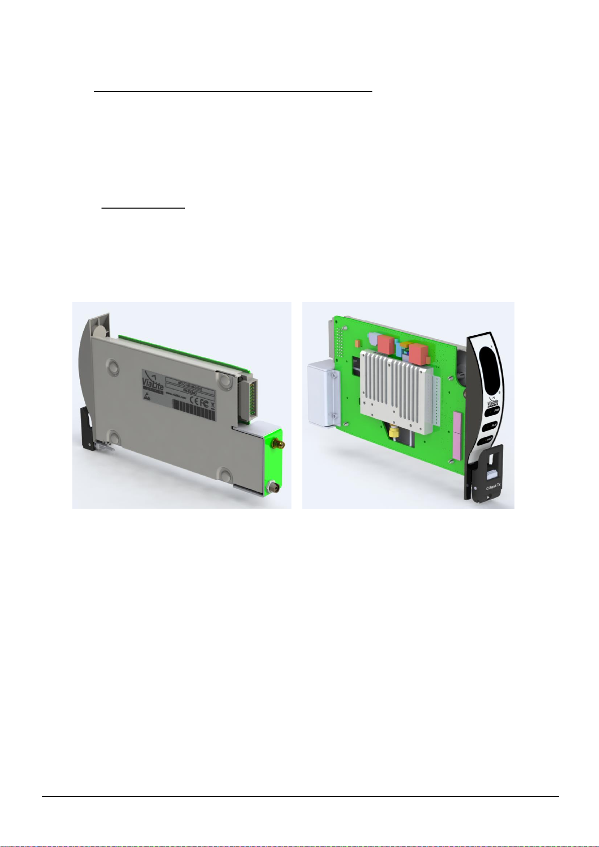
2.1.1 5HP standard plug-in modules .................................................................................................... 6
2.1.2 RF connectors.............................................................................................................................. 7
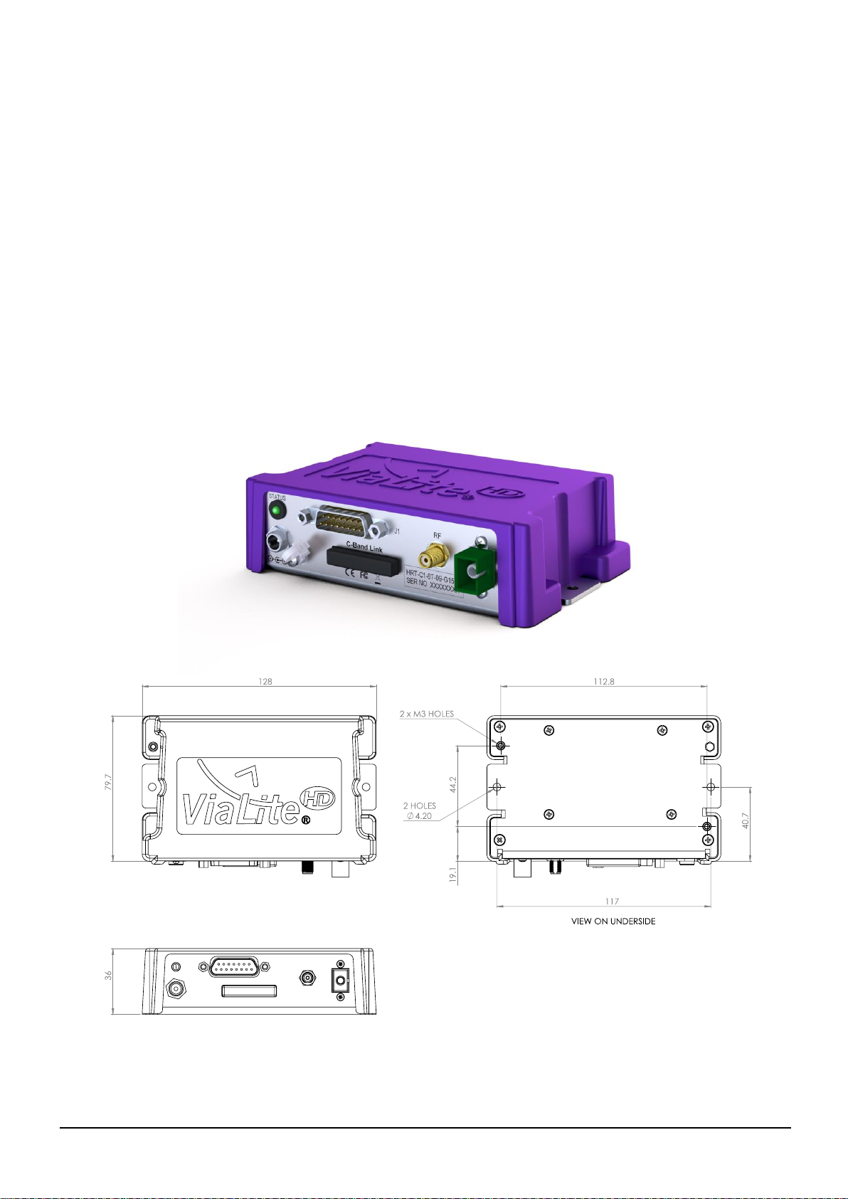
2.1.3 Purple link modules...................................................................................................................... 7
2.2 Fibre optic cable & connectors............................................................................................................... 8
2.2.1 Connecting and disconnecting..................................................................................................... 8
2.2.2 Cleaning optical connectors, cleaning before every use ............................................................. 8
2.2.3 Cleaning optical connectors, high levels of contamination.......................................................... 8
2.2.4 FC/APC Connectors .................................................................................................................... 9
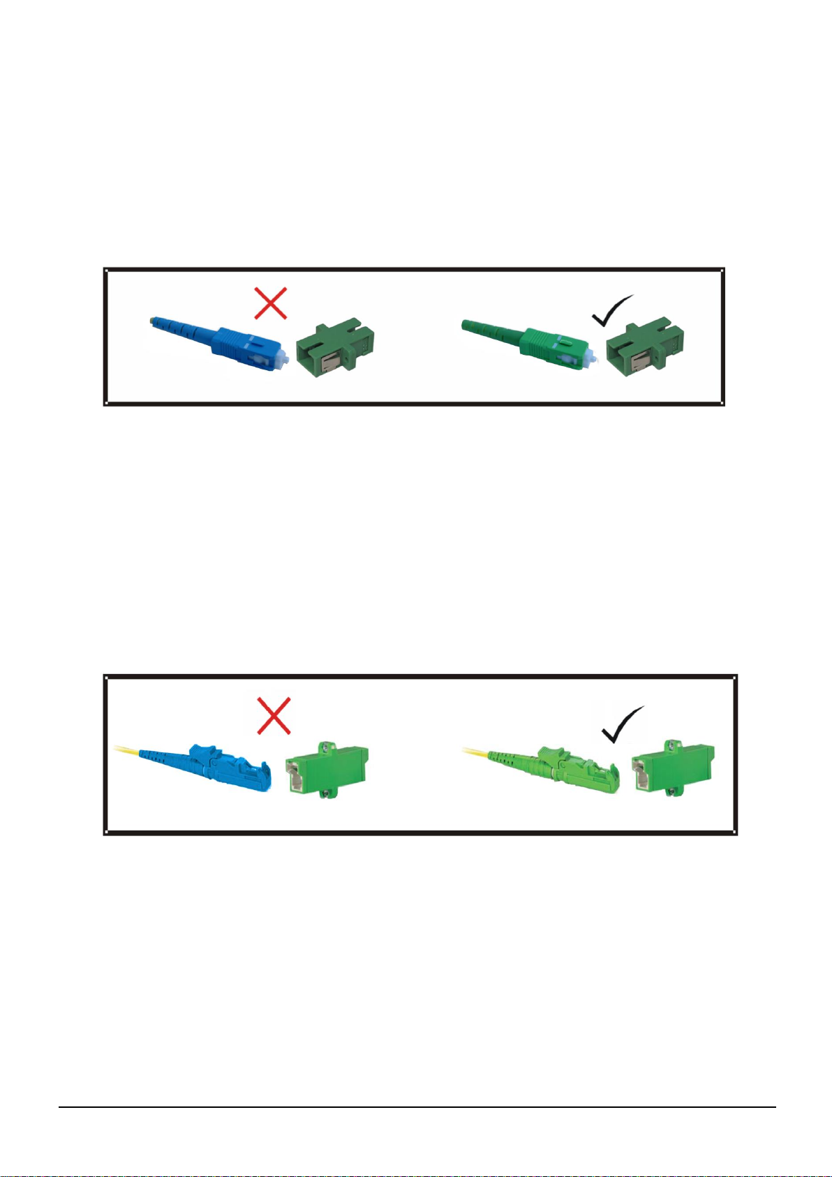
2.2.5 SC/APC Connectors.................................................................................................................. 10
2.2.6 E2000/APC Connectors............................................................................................................. 10
2.2.7 Minimum bend radius................................................................................................................. 10
2.3 Using the RF link module..................................................................................................................... 11
2.3.1 Connecting the module.............................................................................................................. 11
2.3.2 Front panel indicators, plug-in modules..................................................................................... 11
2.3.3 LED indicator, purple modules................................................................................................... 11
2.3.4 Module summary alarm ............................................................................................................. 11
2.3.5 Connecting to the summary alarm............................................................................................. 12
2.3.6 Received light level (RLL) alarm................................................................................................ 12
2.3.7 Module analogue monitor .......................................................................................................... 12
2.3.8 High power and DWDM transmitter modules, thermal load ...................................................... 13
2.3.9 Operating in gain control modes................................................................................................ 13
2.4 Controlling RF modules........................................................................................................................ 14
2.4.1 Manual control, MGC................................................................................................................. 14
2.4.2 Manual control, DIP switch functions......................................................................................... 14
2.4.2.1 DIP switches - receiver MGC...................................................................................... 15
2.4.2.2 DIP switches - transmitter MGC ................................................................................. 15
2.4.2.3 Manual gain control example...................................................................................... 16
2.4.2.4 DIP switches - control................................................................................................. 16
2.4.3 Changing module RF gain......................................................................................................... 17
2.4.4 Software control - via SNMP controller...................................................................................... 17
2.5 LNA/LNB and BUC DC feeds............................................................................................................... 17
2.5.1 LNA/LNB feed - transmitter modules......................................................................................... 17
2.5.2 LNA/LNB feed efficiency - plug-in modules............................................................................... 17
2.5.3 LNA/LNB voltage boost - plug-in modules................................................................................. 18
2.5.4 LNA feed - Purple link modules ................................................................................................. 18
2.5.5 LNA feed –Voltage versus current characteristic ..................................................................... 18
2.5.6 BUC feed - receiver modules..................................................................................................... 18
2.5.7 Manual configuration of LNA/LNB and BUC feeds, plug-in modules........................................ 19
2.6 Module Interface ratings....................................................................................................................... 19
2.6.1 Susceptibility to DC pulses from ViaLiteHD receivers............................................................... 19
2.6.2 Protection of ViaLiteHD equipment from DC pulses.................................................................. 19
2.6.3 Logic interface, TTL 5V.............................................................................................................. 19
2.6.4 Logic interface, I2C.................................................................................................................... 20
2.6.5 Logic interface, Open Drain, output........................................................................................... 20
2.6.6 Power interface, +12V, input...................................................................................................... 20
2.6.7 Analogue interface, laser diode bias, output ............................................................................. 20
2.6.8 Analogue interface, photodiode received light level, output...................................................... 21
2.6.9 Internally generated LNB power supply and tone...................................................................... 21
2.6.10RF connectors............................................................................................................................ 21
2.6.11Optical connections.................................................................................................................... 21