Powtier Controls ACC-6-00 Manual de usuario

Air Curtain
Heater and Fan Controller
Instruction Manual
Copyright © 2005-7 Powtier Controls Limited
This document contains proprietary information which is protected by copyright. All rights reserved. This document or parts thereof may not
be reproduced in any form without written permission of the publishers.
The information in this document is subject to change without notice and should not be construed as a commitment by Powtier Controls
Limited. Powtier Controls Limited shall not be liable for errors contained herein or for incidental or consequential damages in connection
with the furnishing, performance or use of this material.

Powtier Controls Limited Air Curtain Controller
Instruction Manual
Table of Contents
Introduction.................................................................................................................................3
Block diagram.............................................................................................................................3
Description..................................................................................................................................4
Power supply...............................................................................................................................4
Sensor input.................................................................................................................................4
Control output.............................................................................................................................4
User interface..............................................................................................................................4
Installation...................................................................................................................................5
Base unit.................................................................................................................................5
Remote unit............................................................................................................................5
Communication......................................................................................................................5
Protection....................................................................................................................................6
Connection diagram....................................................................................................................6
Connection terminals (base unit)................................................................................................7
Connection terminals (remote unit)............................................................................................8
Layout diagram (base unit).........................................................................................................9
Layout diagram (remote unit)...................................................................................................10
Dimensional drawing (base unit)..............................................................................................11
Operation parameters................................................................................................................12
Control......................................................................................................................................13
Alarms.......................................................................................................................................14
Technical specification.............................................................................................................15
Ordering information................................................................................................................16
Supplier information.................................................................................................................16
ACCIM Page 2 5 March 2007
Issue 1.4

Powtier Controls Limited Air Curtain Controller
Instruction Manual
Introduction
This instruction manual describes a dedicated temperature and fan controller used to control
the air curtain (ACC).
When the measured temperature is lower than the setpoint temperature, the output will cycle
between its minimum and maximum output settings.
All user adjustments are by means of front panel push buttons on the remote control unit, with
indication of setting and measurement by 7-segment LED display.
Block diagram
ACCIM Page 3 5 March 2007
Issue 1.4

Powtier Controls Limited Air Curtain Controller
Instruction Manual
Description
The Air Curtain Controller (ACC) consists of a base unit and a remote unit. The base unit
houses the power supply, sensor input conditioning circuitry, microcontroller, output drive to
heaters and fan, thermal trip protection, Building Management System (BMS) control logic
and interface to the remote unit.
The remote unit forms the operator panel which consists of three 7-segment Light Emitting
Diode (LED) display for temperature and parameters indication and three push buttons for
control and setting adjustments.
All the connections to the controller are via screw terminals.
Power supply
The ACC requires 3 phase 4 wire 415Vac 50/60Hz supply.
Sensor input
A high accuracy Negative Temperature Coefficient (NTC) temperature sensor is supplied as
standard.
Control output
Opto-triac outputs are used for the control of heater output. The rating is 3 phase 3 wire
415Vac, up to 24KW max.
Relay outputs are used for the control of the fan speed; high, medium, low or off.
User interface
The user interface comprises of 3 digits 7-segment red LED display and 3 push buttons.
The 7-segment display is used to indicate measured temperature, setpoint temperature, heater
On/Off setting, fan speed setting. It is also used to show other engineering parameters (in
engineering view mode) such as proportional band, current output power, heatsink
temperature, zero and span reference, air alarm setting, heatsink alarm setting and minimum
power setting.
One push button is used to scroll the parameter display. Two adjustment push buttons "UP"
and "DOWN" are used to increment and decrement the parameters settings.
Please note after 3 minutes of inactivity on the push buttons, the display will revert to
showing air temperature or alarm.
ACCIM Page 4 5 March 2007
Issue 1.4

Powtier Controls Limited Air Curtain Controller
Instruction Manual
Installation
Base unit
The ACC base unit is installed inside the air curtain unit. The ACC remote unit is installed in
a separate housing. Please see layout diagrams and dimensional drawing for fixing.
The distance between the base unit and the remote unit can be up to 50M maximum.
All the electrical connections are via screw terminals. There are 6 sets of connections.
The 3 phase mains supply is connected to the middle of the 1x3 way and left side of the 2x2
way connector marked "R", "Y", and "B" and the neutral is connected to a left side of the 1x3
way connector marked "N".
The heater output is connected to the right side of 1x2 and 2x2 way connector marked
"Load1", "Load2" and "Load3".
The fan output is connected to a 6 way connector marked "N Lo Md Hi".
The sensor input (air sensor) is connected to a 2 way connector marked "AIR" on the base
unit. The sensor is not polarity sensitive.
The BMS control logic (volt-free contact) is connected to a 2 way connector marked "BMS".
The input is normally closed to enable the fan and heater output. The connection is not
polarity sensitive.
The external thermal trip (volt-free contact) is connected to a 2 way connector marked "Trip".
The input is normally closed to enable the fan and heater output. The connection is not
polarity sensitive.
Remote unit
The remote unit is connected to the base unit through 1 set of 4 way connectors marked "B, A,
0V and 7V".
For multiple base units sharing a single remote unit, the 7V supply connection should be
connected to just one base unit or it can be supplied locally using a separate 5.5 to 10V
100mA dc supply.
Communication
The communication link between the base and the remote unit are designed to accommodate
multiple base units sharing a single remote unit.
If there is more than one base unit sharing the same remote unit, each base unit must have its
own unique address. There is a 4 way dual-in-line switch marked ADDR on the base unit.
This can be used to set the base unit address from 0 to 15.
The left most switch is the Least Significant Bit and the right most switch is the Most
ACCIM Page 5 5 March 2007
Issue 1.4

Powtier Controls Limited Air Curtain Controller
Instruction Manual
Significant Bit. To change the address to 0, set all 4 switches to 0 or Off. To change the
address to 15, set all 4 switches to 1 or On. To change the address to 1, set the left most
switch to On and the rest to Off. To change the address to 8, set the right most switch to On
and the rest to Off.
The base unit is shipped with a default address of 0.
Protection
There are two high speed fuses on the base unit to protect the switching devices for the heater.
External circuit breaker with the appropriate rating should be installed for the protection of
the installation.
Connection diagram
ACCIM Page 6 5 March 2007
Issue 1.4

Powtier Controls Limited Air Curtain Controller
Instruction Manual
Connection terminals (base unit)
Terminal Description
R 3 phase supply
Y 3 phase supply
B 3 phase supply
N Neutral from mains
Load1 Heater phase 1
Load2 Heater phase 2
Load3 Heater phase 3
N Neutral to fan
Lo Fan - low speed
Md Fan - medium speed
Hi Fan - high speed
BMS BMS control logic, normally closed (volt-free contact)
BMS BMS control logic, normally closed (volt-free contact)
AIR Air sensor (non-polarised)
AIR Air sensor (non-polarised)
Trip External thermal trip, normally closed (volt-free contact)
Tip External thermal trip, normally closed (volt-free contact)
B RS485 Comms to remote unit
A RS485 Comms to remote unit
0V Supply to remote unit
7V Supply to remote unit
ACCIM Page 7 5 March 2007
Issue 1.4

Powtier Controls Limited Air Curtain Controller
Instruction Manual
Connection terminals (remote unit)
Terminal Description
7V Supply from base unit
0V Supply from base unit
B RS485 Comms to base unit
A RS485 Comms to base unit
ACCIM Page 8 5 March 2007
Issue 1.4
Powtier Controls Limited Air Curtain Controller
Instruction Manual
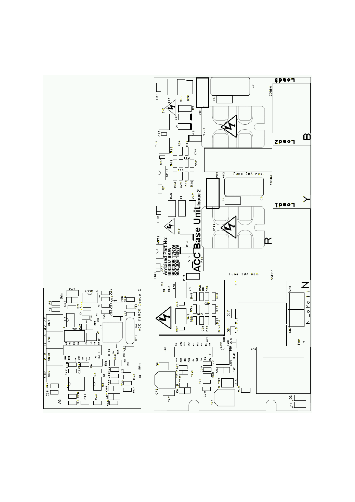
Layout diagram (base unit)
ACCIM Page 9 5 March 2007
Issue 1.4

Powtier Controls Limited Air Curtain Controller
Instruction Manual
Layout diagram (remote unit)
ACCIM Page 10 5 March 2007
Issue 1.4
Este manual sirve para los siguientes modelos
4
Tabla de contenidos
Otros manuales de Controladores de temperatura de Powtier Controls


