Potter PS100-2 Manual de usuario

MFG. #5400932 - REV D-1
12/10
PRINTED IN USA PAGE 1 OF 3
PS100-2
PRESSURE TYPE FLOW SWITCH
Installation
The Potter PS100 PressureActuated Switches are designed primarily to detect
a decrease from normal system pressure in automatic re sprinkler systems.
A typical application is for an alarm initiating device that is used on a wet
system with excess pressure. The PS100-2 has two SPDT switches factory
set to operate on a pressure drop at 90 PSI (6,2 BAR). See section heading
Adjustments and Testing if other than factory set point is required.
1. Connect the PS100 to the system side of any shutoff or check valve.
2. Apply Teon tape to the threaded male connection on the device.
(Do not use pipe dope)
3. Device should be mounted in the upright position.
(Threaded connection down)
4. Tighten the device using a wrench on the ats on the device.
Wiring Instructions
1. Remove the tamper resistant screw with the special key provided.
2. Carefully place a screwdriver on the edge of the knockout and sharply
apply a force sufcient to dislodge the knockout plug. See Fig. 9
3. Run wires through an approved conduit connector and afx the
connector to the device. A NEMA-4 rated conduit tting
is required for outdoor use.
4. Connect the wires to the appropriate terminal connections for the
service intended. See Figures 2,4,5,7, and 8. See Fig. 6 for two
switch one conduit wiring.
UL, cUL, and CSFM Listed, FM and LPC Approved, NYMEA
Accepted, CE Marked
Dimensions: 3.78" (9.6cm)W x 3.20" (8.1cm)D x 4.22" (10.7cm)H
Conduit Entrance: Two knockouts provided for 1/2" conduit.
Individual switch compartments and ground screw
suitable for dissimilar voltages.
Enclosure: Cover- Die-cast with textured red powdercoat nish, single
cover screw and rain lip.
Base- Die-cast
Pressure Connection: Nylon 1/2" NPT male
Factory Adjustment: Operates on decrease at 90 PSI (6,2 BAR)
Pressure Range: 25-175 PSI (1,7 - 12,1 BAR)
Differential: Typical 2 lbs. at 25 PSI (,14 at 1,7 BAR)
8 lbs at 175 PSI (,55 at 12,1 BAR)
Maximum System Pressure: 300 PSI (20,68 BAR)
Switch Contacts: Two SPDT (Form C)
10.1 Amps at 125/250VAC, 2.0 Amps at 30VDC
Environmental Specications:
NEMA4/IP66 Rated Enclosure - indoor or outdoor when
used with NEMA-4 conduit ttings.
Temperature range: -40°F to 140°F (-40°C to 60°C)
Tamper: Cover incorporates tamper resistant fastener that requires
a special key for removal. One key is supplied with each device.
For optional cover tamper switch kit, order Stock No. 0090200.
See bulletin #5401200 PSCTSK.
Service Use:
Automatic Sprinkler NFPA-13
One or two family dwelling NFPA-13D
Residential Occupancy up to four stories NFPA-13R
National Fire Alarm Code NFPA-72
Potter Electric Signal Company • St. Louis, MO •Customer Service: 866-572-3005 • Tech Support: 866-956-0988 •Canada 888-882-1833
•www.pottersignal.com
Adjustment And Testing
The operation of the waterow pressure switch should be tested upon
completion of installation and periodically thereafter in accordance with
the applicable NFPA codes and standards and/or the authority having
jurisdiction (manufacturer recommends quarterly or more frequently).
Note: Testing the PS100 may activate other system connected devices.
The use of a Potter BVL (see product bulletin 8900067 for details) is
recommended to facilitate setting and testing of the PS100 pressure
switch. When a BVL (bleeder valve) is used, the pressure to the switch
can be isolated and bled from the exhaust port on the BVL without
effecting the supervisory pressure of the entire system. See Fig. 3
The operation point of the PS100 Pressure Switch can be adjusted to any
point between 25 and 175 PSI (1,7 - 12,1 BAR) by turning the adjustment
knob(s) clockwise to raise the actuation point and counter clockwise to
lower the actuation point. Both switches operate independent of each
other. Each switch may be independently adjusted to actuate at any point
acrosss the switch adjustment range. Initial adjustment can be made
with a visual reference from the top of the adjustment knob across to the
printed scale on the switch bracket. Final adjustments should be veried
with a pressure gauge.
Ordering Information
Model Description Stock No.
PS100-2 Pressure switch with two SPDT contacts 1341005
Hex Key 5250062
Cover Tamper Switch Kit 0090200
BVL Bleeder valve 1000018
MFG. #5400932 - REV D-1
12/10
PRINTED IN USA PAGE 2 OF 3
PS100-2
PRESSURE TYPE FLOW SWITCH
Typical Sprinkler Applications
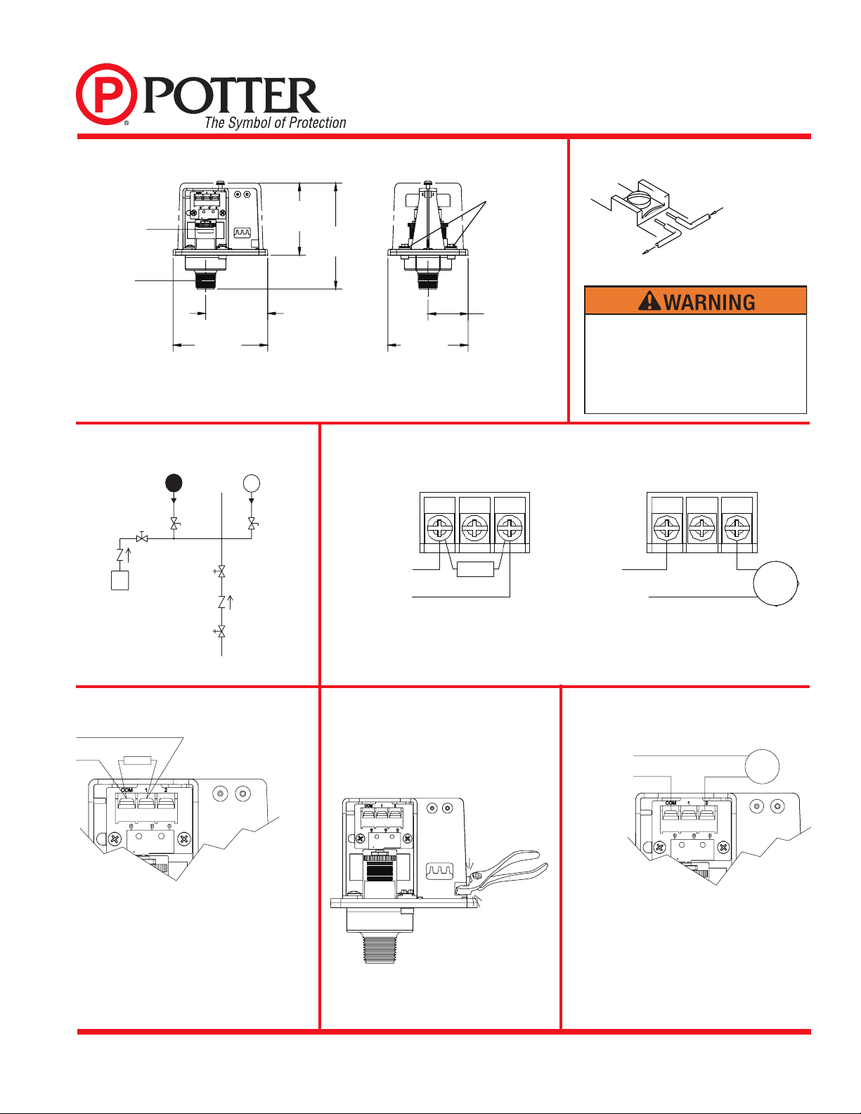
Switch Clamping Plate Terminal
Dimensions
OUTGOING INCOMING
DWG# 923-3
Fig. 1 Fig. 2
Fig. 3
PS100
PRESSURE
DROP ALARM
SWITCH
SHUT-OFF
VA LV E
BLEEDER
TEST VA LV E
BVL
CHECK
VA LV E
EXCESS
PRESSURE
PUMP
PS120 PRESSURE
SUPERVISORY
SWITCH
BLEEDER
TEST VA LV E
BVL
DWG #925-1A
OS & Y
VA LV E
OS & Y
VA LV E
CHECK
VA LV E
WATER
SUPPLY
Fig. 4
An uninsulated section of a single conductor
should not be looped around the terminal and
serve as two separate connections. The wire
must be severed, thereby providing supervision
of the connection in the event that the wire
becomes dislodged from under the terminal.
Typical Connections
DWG# 928-4
Break out thin section of divider to
provide path for wires when wiring both
switches from one conduit entrance.
One Conduit Wiring
Fig. 6
Waterow Signal Connection
EOLR
TO FIRE ALARM PANEL
DWG# 928-2
Fig. 5 Fig. 7
Local Bell For Waterow Connection
POSITIVE DC
OR HOT AC
BELL
NEGATIVE DC
OR NEUTRAL AC
LINE LOAD
DWG# 932-2
NOTE: To prevent leakage, apply Teflon tape sealant to male threads only.
2.87
[72.97]
4.22
[107.19]
2.48
[62.87]
3.78
[95.89]
3.20
[81.28]
1.60
[40.64]
GROUND
SCREWS
DWG# 930-1
1/2" NPT
ADJUSTMENT
KNOB
BELL
COM1 2COM1 2
EOLR
TO FIRE
ALARM
PANEL
POSITIVE DC
OR HOT AC
NEGATIVE DC OR
NEUTRAL AC
LINE LOAD
OPEN CIRCUIT CLOSES ON ALARMRIN
G
A
L
OCA
L BELL
WITH NORMAL
SYSTEM
PRESSURE
APPLIED
-TERMINAL
2 CLOSES ON
PRESSURE DROP.
DWG# 932-1

MFG. #5400932 - REV D-1
12/10
PRINTED IN USA PAGE 3 OF 3
PS100-2
PRESSURE TYPE FLOW SWITCH
Fig. 8
DWG#928-5
Fig. 9
Removing Knockouts
Changing Pressure (with normal system pressure)
C
C12
SWITCH ONE SWITCH TWO
C
C12
DWG# 932-3
Engineer/Architect Specications Pressure Type
Waterow Switch
Pressure type waterow switches; shall be a Model PS100-2 as
manufactured by Potter Electric Signal Company, St. Louis, MO.,
and shall be installed on the re sprinkler system as shown and or
specied herein.
Switches shall be provided with a ½" NPT male pressure connection
to be connected to the excess pressure supply line on the system
side of any shut-off or check valve. A Model BVL bleeder valve as
supplied by Potter Electric Signal Company of St. Louis, MO., or
equivalent shall be connected in line with the PS100-2 to facilitate
testing of the PS100-2.
Pressure type waterow switches shall have a maximum service
pressure rating of 300 PSI (20,68 BAR) and shall be factory adjusted
•Installation must be performed by qualied personnel and in
accordance with all national and local codes and ordinances.
•Shock hazard. Disconnect power source before servicing.
Serious injury or death could result.
•Read all instructions carefully and understand them before
starting installation. Save instructions for future use. Failure
to read and understand instructions could result in improper
operation of device resulting in serious injury or death.
•Risk of explosion. Not for use is hazardous locations.
Serious injury or death could result.
•Do not tighten by grasping the switch enclosure. Use wrenching
ats on the bushing only. Failure to install properly could
damage the switch and cause improper operation resulting in
damage to equipment and property.
•To seal threads, apply Teon tape to male threads only. Using joint
compounds or cement can obstruct the pressure port inlet and result
in improper device operation and damage to equipment.
•Do not over tighten the device, standard piping practices apply.
to operate on a pressure decrease of 10 PSI (14,5 BAR).
Pressure switch shall have two Form C contacts, switch contact rating
at 10.1 Amps at 125/250 VAC. 2.0 Amps at 30 VDC.
Pressure type waterow switches shall have two conduit entrances,
one for each individual switch compartment to facilitate the use of
dissimilar voltages for each individual switch.
The cover of the pressure type waterow switch shall be zinc die-cast
with rain lip and shall attach with one tamper resistant screw. The
pressure type waterow switch shall be suitable for indoor or outdoor
service with a NEMA-4/IP66 rating.
The pressure type waterow switch shall be UL, ULC, and CSFM
listed, FM and LPC approved and NYMEA accepted.
#1: Closed under normal system pressure.
#2: Open under normal system pressure, closes on pressure
drop. Use as waterow detector.
Otros manuales de Cambiar de Potter

Potter
Potter VSR-SG Manual de usuario

Potter
Potter PS40 SERIES Manual de usuario

Potter
Potter RBVS Manual de usuario

Potter
Potter ADPS-300-2S Manual de usuario

Potter
Potter PS10 Series Manual de usuario

Potter
Potter VSR-F Manual de usuario

Potter
Potter PS40 SERIES Manual de usuario

Potter
Potter PAD100-DRTS Manual de usuario

Potter
Potter VSR-F Manual de usuario

Potter
Potter PS120 Series Manual de usuario


