Parking Facilities PF9700 Manual de usuario

Operaon and Maintenance Manual
Revision 10.0 2020
THIS DOCUMENT CONTAINS IMPORTANT
INFORMATION. IT MUST BE KEPT WITH THE GATE
AT ALL TIMES.

Address: Tel: Email: Web:
Safety Features
Thank you for purchasing one of our perimeter security products.
Your gate will provide safe and reliable service and peace of mind provided that the following
instructions and guidance is followed.
Your gate is fied with a range of safety devices designed to prevent accidents or injury, none
the less the area in the immediate vicinity of the gate should be treated as potentially hazardous
and avoided whenever the gate is moving
Explanaon of safety features and gate reacon:
Dual Height Photocells – (across clear opening) stops gate closing and reverses to the fully
open posion.
CAT 3 Safety Edges – Safety edges are direcon dependent and will stop gate and reverse
in the opposite direcon to which the gate was moving.
Emergency Stop Buon – located on the front of the gate tower this can be used before an
incident happens.
Safe use warnings:
1. Do not allow children/people with physical or mental impairment to play on or near the
gate. Gates are designed for vehicular use only
2. Keep remote control devices away from children.
3. Do not try to pass through/over/under the moving gate.
4. Do not stop unnecessarily when passing through the gate.
5. Only operate the gate controls when in view of the gate.
6. Do not aempt to interfere or modify the gate from the factory setup.
7. Make sure the gate is maintained by a trained and qualified powered gate specialist at the
prescribed 6 monthly intervals and that services are recorded in this manual’s log.
8. If any sign of malfuncon occurs switch off the gate, manually release it and contact a
trained and qualified powered gate specialist immediately.

Address: Tel: Email: Web:
Safe Use Instrucons
To open the gate:
The gate may be opened using the Open push buon input, panel mounted keypad buon, exit loop
or radio fob (if fied). The gate will smoothly accelerate to fast speed unl the intermediate limit is
reached, at which point the gate will smoothly decelerate for the remainder of the travel distance.
The gate may be closed using the Auto-Close funcon, the Close buon input, panel mounted
keypad buon or radio fob. The gate will smoothly accelerate to full speed unl the intermediate
limit is reached, at which point the gate will decelerate for the remainder of the travel distance.
If a safety device is acvated (i.e. safety edge or photocell) during the closing cycle the gate will stop
& return to the fully open posion. The gate may only be closed once the obstrucon has been
removed.
To close the gate:
If a safety device is acvated (i.e. safety edge or photocell) during the closing cycle the gate will stop
& return to the fully open posion. The gate may only be closed once the obstrucon has been
removed.
The gate can also be closed by external devices but also using the down arrow on the front of the
control panel.

Address: Tel: Email: Web:
Manual operation:
In the event of a power cut or other fault it will be necessary to move your gate in manual mode.
Manual operation should only be aempted by a responsible adult. Before doing this always
switch the system off at the main isolator, your installer will have shown you where this is on your
system.
You can now move the gate manually. Only move the gate very slowly, no faster than it moves in
normal use. Your installer will have demonstrated this at handover.
To return the gate to automac operaon (when the power is restored) simply follow the steps
above in reverse order:
120
Emergency opening: 120 mm
First you need to raise the automatic drop bolt as this is fail secure, to do this, use
the override key provided with the lock to unlock the cylinder, you can then slide
the bolt up by 120mm an out of the way, once this is done follow the below
instructions to manually open the gate leaf

Address: Tel: Email: Web:
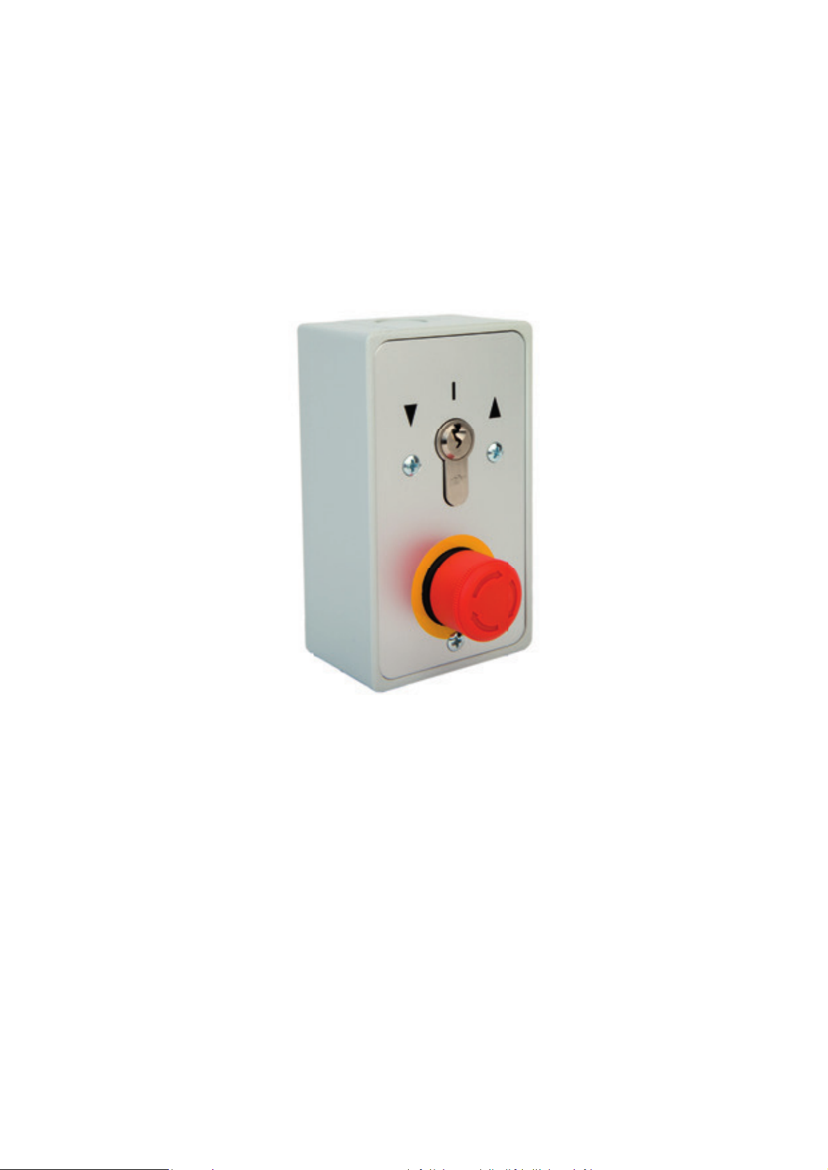
Key Switch
If a fault happens to appear on the controller that relates to a safety device the gate will more than
likely only operate in deadman mode. on the front of the tower there is a key switch that can be
turned either way to open the gate in deadman operation overriding the faults. if you let go of the
key switch whilst the gate is operating the gate will stop until you continue turning the keyswitch. if
there is no fault on the gate the key switch will give a normal automatic open and close signal.
If you have two gates working in master and slave mode the key switch will only operate the gate
that it is attached to.
Stop Button
If you have an issue and need to stop the gate immediately there is a stop button on the gate that
will stop the gate and will not allow it to operate until its released. once pressed in you twist the
button and it will release. once released you will need to give the gate another open or close signal
for it to start operating again.
If you have two gates working in master and slave mode the stop button will only operate the gate
that it is attached to.

Address: Tel: Email: Web:
End User Regular Safety Checks
General:
Keep the areas adjacent to the gate clear of obstrucons at all mes, cut back plants and weeds that
might interfere with the gate and its safety sensors. Keep the photo electric beam covers clean.
Safety checks:
These user safety checks should be conducted every [few weeks] by a responsible adult who has
been shown how to do the checks by a trained and qualified powered gate specialist. We will
demonstrate the user checks to you as part of the handover process.
[Insert instrucons]

Address: Tel: Email: Web:
Engineer Planned Preventative Maintenance Schedule
Your gate will need to receive regular planned preventative maintenance in order to remain in safe
and reliable service. The maintenance outlined below should only be conducted by a trained and
qualified powered gate specialist who is familiar with 9700 automation equipment and has the
necessary test equipment. [insert company] can provide this service and you will have been offered
a maintenance contract as part of the supply process. If the maintenance outlined below is not
completed, [insert company] cannot accept responsibility for injuries, accidents or breakdowns
caused by lack of maintenance.
You are reminded that, as the person in control of the gate, you have a legal duty of care to users
and to visitors to the premises (including trespassers). If the gate is not kept safe, any party whose
property is damaged or who is injured by the gate is likely to be able to sue for damages.
If the gate is part of an undertaking (such as at rented property), the person in control of it will have
additional duties under section 3 of the Health and Safety at Work Act 1974 to keep the gate
maintained in a safe condition.
If the premises are also a workplace, there are specific duties under regulation 5 and 18 of the
Workplace (Health and Safety and Welfare) Regulations 1992.
Failure to meet duties imposed by health and safety legislation can result in criminal proceedings.
A maintenance log is provided at the end of this book to record completed maintenance. Please
make sure the maintenance log is completed and signed on completion of any maintenance work.
At 6 month intervals:
Inspections:
Check and grease bearing at the top
Check that all gearbox and motor mountings are tight and secure
Check that the gate manual release is still functioning
Check that the gate moves stable and freely when the manual release is engaged and power is
switched off!
Check all running gear fixings are tight and secure
Check flashing beacon is working
Check that the emergency stop button works
Check all safety edges work and are working for the correct direction of travel
Check the photocells are working and in the correct direction of travel
Check that no one has made the gate unsafe by speeding it up past the factory settings
Check that the control program has not been modified such as to make the gate unsafe. Please
consult the manufacturer if in doubt
Call the manufacturer to talk this through if in doubt, use common sense and it is better to check
everything twice!

Address: Tel: Email: Web:
Lubricaon:
Any grease nipple (All other items are “sealed for life” and require no lubricaon)
Funcon checks:
•Overall gate structure and plumb of hinges
•Lubricate hinges and unit pivots
•Gearbox oil level
•Funcon of manual release
•Torque seng on control unit
•Obstacle detecon effecveness (measure forces)
•Overall funcon/condion of actuators
•Funcon and condion of safe edges
•Photocells internal and external
•Sealing of photocell covers and cable entry
•Wire terminaons in control panel
•Sealing of control unit cover and cable entries
•Condion of all wiring and juncon boxes
•Funcon of all controls – transmiers, loop and intercoms
•Security and effecveness of all earth connecons
•Test earth fault loop resistance and RCD funcon
•Reassess and check the ongoing validity of the hazard assessment
Performance tests:
Force Test (Not a legal requirement but advisory)
Check that the manual release is working
Ensure that the gate is running smoothly
Check Flashing Beacon is working

Address: Tel: Email: Web:
Handover Check list
The following items have been explained to the client:
□How to operate the gate.
□How to isolate the power to the gate.
□How to manually release the gate.
□How the safety features of the gate work.
□How to avoid any residual hazards associated with the gate.
□How to use the acvaon devices.
□How to change the baeries on remotes etc.
□How to change the keypad pin code.
□How and when to perform the required safety checks.
□Other [insert]
The following items have been passed to the client.
□Manual release instrucons.
□Intercom user manual.
□Declaraon of Conformity.
□User warnings and residual hazard idenficaon.
□Planned Preventave Maintenance instrucons.
□Maintenance log.
□Other [insert]
Installer Name: Date:
Signature:
Client Name: Date:
Signature:
ü
The following items have been completed by the installer: [ck]
□ Carried out site risk assessment prior to installation
□ Carried out site risk assessment after installation and carried out necessary
modification to eliminate hazards found
□ Carried out the installation as per the manufacture’s recommendations

Address: Tel: Email: Web:
Component list
Drive unit: PFL Swing Gate Drive 3 Phase
PFL Drive 3 Phase /550Watts /60Nm Torque /58 RPM /2.3A Nominal Current
35mm Axle
Photo beams: Witt Argos-T/ Argos-R TX & RX Through Beam
Safe edge: ASO 65mm profile
Encoder: Feig TST PD-ME-B
Control panel: Feig TST FUZ 2 B
Otros manuales para PF9700
1
Tabla de contenidos
Otros manuales de Cercas y portones de Parking Facilities