Parametric TCR Manual de usuario

TCR Users Manual
V2.2
Introduction
TCR are solar powered radar object counters with integrated LoRaWAN®
connectivity.
The system includes powerful radar signal processing that enables bi-directional
counting of moving objects in distances up to 10m. Objects can be categorized into
up to 4 groups with speed and object size filters. Counter values are transmitted in
regular intervals to the LNS (LoRaWAN® Network Server).
TCR GEN2 is a very versatile radar counting system. It enables various
applications such as people counting, traffic statistics, use of sports facilities or
even security applications.
TCR-Sxx types come with an integrated solar charging unit including tempered
battery. The battery is used to backup up to 4 foggy days. The system can be
installed very flexible on different locations including remote areas without any
electricity.
Installation
To achieve the most accurate measurement possible, planning the installation is
essential. This chapter therefore contains information on the correct choice of
location for the TCR traffic counter.
To achieve the most accurate measurement possible, planning the installation is
essential.
Horizontal or Top Down?
The devices can be operated both directly next to the road or elevated and looking
down from above. We recommend using a laser measuring tool or a laser pointer to
align the device correctly.

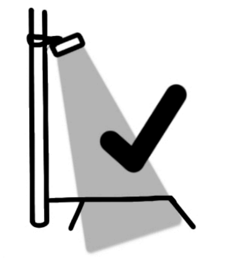
When mounted on a pole or mast you should point the
sensor to the middle of the road (center line). This can be
done easily by adjusting the tiltable bracket MT80-15. The
bracket can be placed about 3-4 meters above ground.
Please check the max range of the sensor. Important:
The pole must not move in the wind
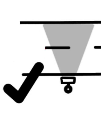
When mounted next to the street we recommend a
mounting height of 1.2-1.5m above ground. Line of sight
should be completely horizontal.
Important Rules
The device works best when the following rules are observed.
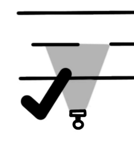
Lateral to movement__
TCR are side radars that detect motion from both
directions simultaneously. The movement should be
linear. Therefore place the sensor parallel to the
movements direction and keep away from curves,
crossings, driveways
50cm distance
The sensor must be at least 50cm away from the target to
avoid signal overload.
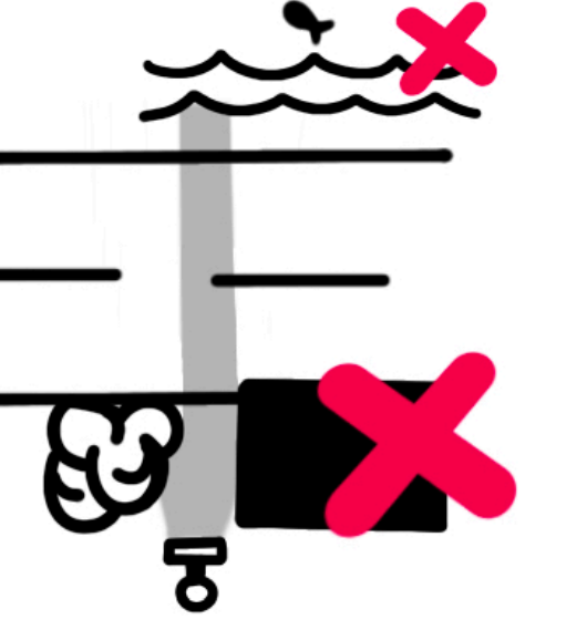
Avoid obstacles in FOV
Make sure there are no obstacles such as walls, street
signs, shrubberies, trees in the field of view. When placed
beside water the device might detect the waves.

LTR vs RTL
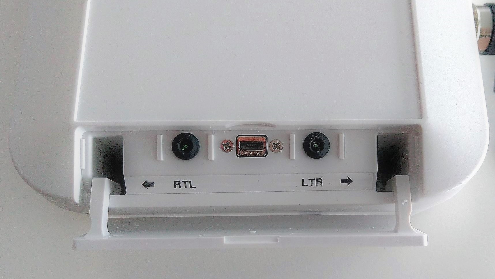
The TCR traffic counters distinguish between 2 directions.
RTL = objects which come from the right and disappear to the left. The left LED
will pulse once in this case.
LTR = objects which come from the left and disappear to the right. The right
LED will pulse once in this case.
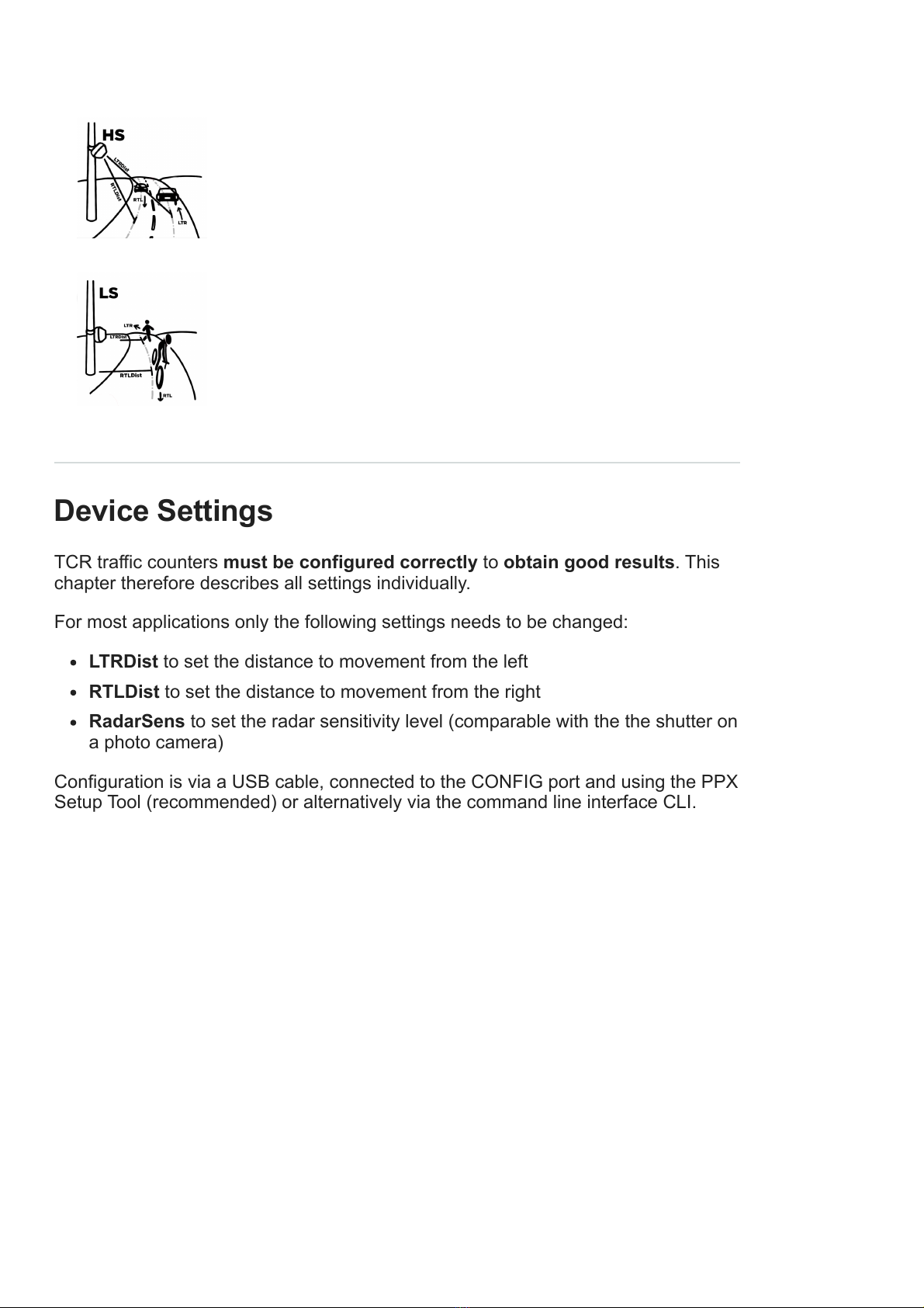
Measure distance to lanes
In order for the device to determine the velocities, the distance to the object must
be known. The distance can be determined with a tape measure or a laser distance
meter. Measurements are taken from the middle of a track to the front of the device.
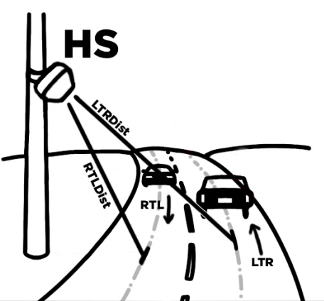
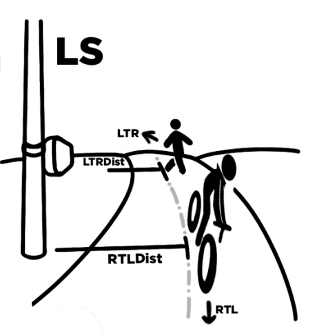
RTLDist = Distance in cm to the RTL movement line.
LTRDist = Distance in cm to the LTR movement line.

Situation
Two lanes, cross traffic (2L2D) This is typical for HS
applications such as measuring traffic on interstate
roads. RTLDist and LTRDist are different.
Cross traffic on one lane (1L2D)
This is typical for low speed traffic (LS) measuring
bicycle lanes or small paths. In this case get the
distance to the center of the track and set RTLDist and
LTR Dist to the same value.
Device Settings
TCR traffic counters must be configured correctly to obtain good results. This
chapter therefore describes all settings individually.
For most applications only the following settings needs to be changed:
LTRDist to set the distance to movement from the left
RTLDist to set the distance to movement from the right
RadarSens to set the radar sensitivity level (comparable with the the shutter on
a photo camera)
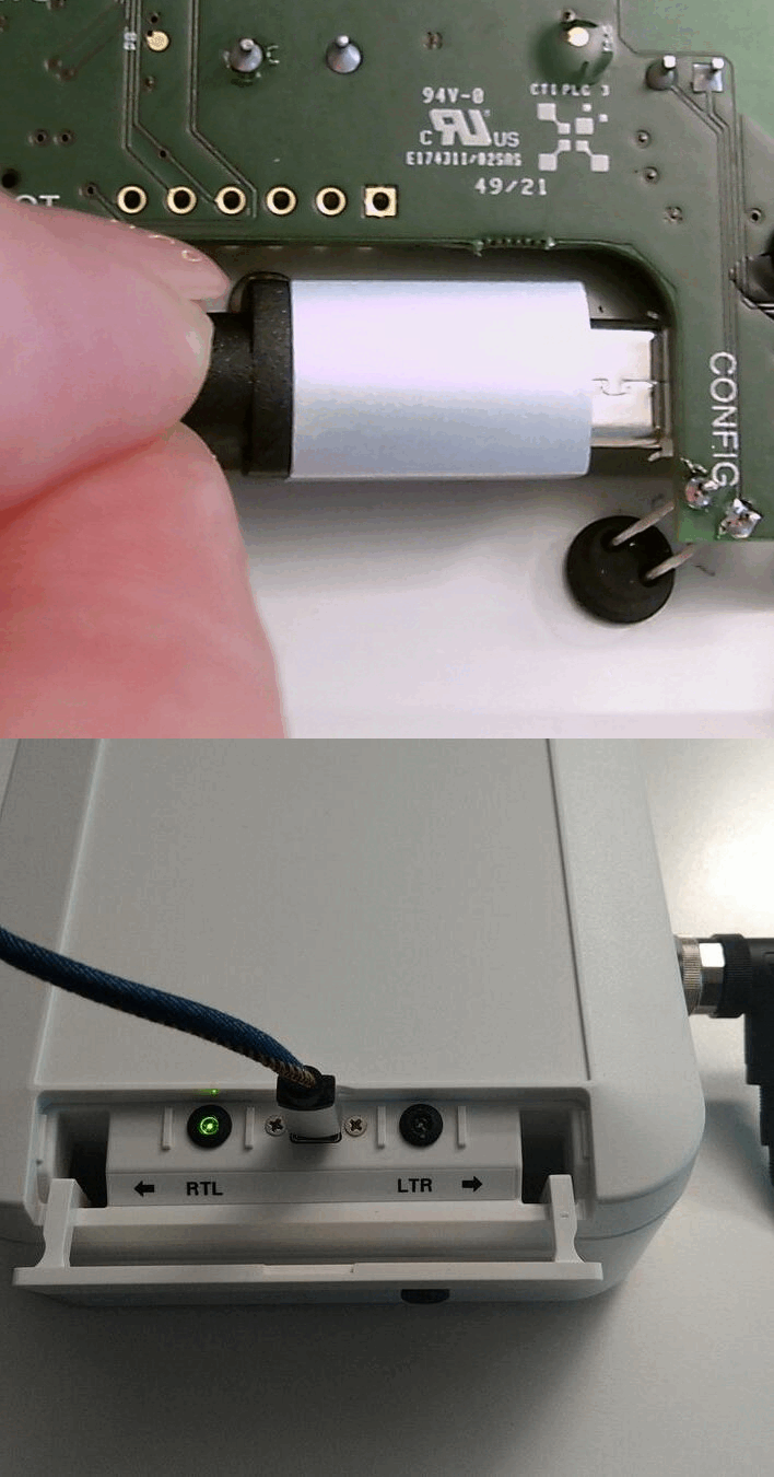
Configuration is via a USB cable, connected to the CONFIG port and using the PPX
Setup Tool (recommended) or alternatively via the command line interface CLI.

Note: On first generation TCR units (TCR-LS, TCR-LSS, TCR-HS, TCR-HSS), the
configuration port is located on the main board. To connect the USB cable, the unit
must be opened.
Symbols used
Setting can be changed over USB with the PPX Setup Tool
Setting can be changed over USB using the TCR Command Line Interface
Setting can be changed remotely by sending TCR LoRaWAN Config
Downlink Commands
Application Settings
Operation Mode
You can select different types of uplink behaviour using the Operation Mode setting.

Mode Description Applications
Timespan The device will accumulate vehicles or
people counting over a certain time.
Then the counter values will be
transmitted over the LoRaWAN Network.
Time period is defined by the LoRaWAN
Uplink Interval Setting.
Most
Applications
use this mode
NotZero Same as Timespan Mode, but the
uplinks will be skipped if there is no
count during the Uplink Interval Period.
The setting can be used to reduce
uplinks for LoRaWAN networks with
limited number of allowed
uplinks/downlinks per day. As the radar
is the largest contributor to energy
consumption, this setting will not have a
noticeable energy saving effect.
Reducing
uplinks
Trigger Sends an uplink immediately when an
object is detected. Unfortunately, the
LoRaWAN standard does not allow
uplinks to be sent in succession at any
speed. Instead, the duty cycle must be
observed. This also applies to this
mode. This means that a trigger is only
executed immediately if there was a
sufficiently long waiting time without
counts beforehand (something like 3
minutes).
Train
detection
Security
Applications
Hold-Off
The hold-off function has been introduced to the device firmware to be able to count
connected vehicles (trains, trailers) as one instead of multiple counts.
Hold-off is enabled by entering a value bigger than zero.
As an example: If Hold-off time is set to 10 seconds the device will increase the
counters as soon as an object has been detected. Then the radar will be off for 10s
.
Value range: 1-600s (0 = disabled).
Default: 0

Auto-Zero
The Auto-zero Timeout will set the account to zero after this time has elapsed. This
is useful if you are using confirmed uplinks. If the uplinks fail, the counter will be
reset to zero after this time.
Default: 120min
Totalizer
This setting defines how to increment the counter values.
Totalizer Counter Reset
Disabled Counter values represent
object counts during
the last time period
After a LoRaWAN Uplink
ACK is received the counter
values are cleared.
Enabled Counter values start with
0 and go up to 65535
max.
Reset counters with
a LoRaWAN Downlink
Command
Default: Disabled
Fallback Category
We try to measure object size and speed. In some situations, however, it is not
possible to determine the size and speed in addition to the direction of movement.
This is mainly if the object is too fast or covers the field of view (FOW). In this
cases, no classification into categories is made and instead the counter of
the fallback category is increased.
Try to place the sensor a little further away from the object so that the objects fits
into the FOW.
Traffic Categories
Criteria defining each type of detection. The radar determines the category based
on the speed and size of the object.
Low Speed device: You can only select two categories (People and Two-Wheelers)
High Speed device: You can select all 4 categories (People, Two-Wheelers, Cars,
HGV)

Important: These settings will need to be changed depending on where the radar
is installed, what you are trying to detect and the type of vehicles likely to pass
underneath.
Radar Settings
Radar Enabled
Radar on by default
Channels
1 set by default
2 if you have a radar in the same
Sensitivity
After entering LTRDist and RTLDist the sensitivity is automatically determined
based on those values. The further the distance to the measurement, the higher the
sensitivity.
Note: Small adjustments of sensitivity can be done manually. If the ratio (sensitivity
vs. RTL/LTR) is not correct, the radar may incorrectly categorize the measured
object.
Beam Angle
Beam size from left to right
Note: In areas where you may have obstacles in the way, you may need to narrow
the angle of the beam.
Beam Directions
Can be offset by up to 30 degrees in any direction. Once again cater for things link
tree and things in the way.
LTRDist
Distance between the radar surface and the object you are trying to detect
approaching from the left.
LTRDist

Distance between the radar surface and the object you are trying to detect
approaching from the right.
Note: If you get inaccurate measurement data, check the accuracy of the distance
settings .
see more instruction: Measure distance to lanes
Autotune
Turn on autotune to allow the radar to adjust the sensitivity.
If the sensitivity is to high, the object might blur and therefore gets too big (Size
value) If the distance is incorrect the size get too big too.
With Autotune enabled the Radar Sensitivity will be controlled automatically. It’s
comparable to the automatic exposure setting at a photo camera.
LoRaWAN Settings
LoRa Modem Enabled
LoRa Modem on by default
Uplink Internval (10min)
Time span of the counts that are sent
Device Class
Class A Device:
Class B Device:
Class C Device:
Confirmed Uplinks
ON:
OFF:
ADR Enabled
ON:

OFF:
RTC Timesync Enabled
ON:
OFF:
Operation Mode (mode)
TCR can be operated in 3 different modes.
Mode Description Used for
Timespan Device is counting during a certain
time interval
(see lora_interval setting). After the
time is up, counter values are
transmitted.
Default behavior.
This can be used
for creating
histograms or
controlling actors
like street lights.
NotZero Same as Timespan but uplinks are
blocked as long as there is no
movement.
This can be used to
save uplinks or
energy.
Trigger This will send an uplink as soon as
an object has been detected
This can be used
for alam
applications.
Note: Trigger mode is limited by the LoRaWAN® standard. It is not possible to
transfer as many times and in arbitrarily short intervals. (See ETSI Duty Cycle for
more information)
Hold-Off Timer (holdoff)
This function is used to filter fast consecutive counts.
As an example, if Hold-off time is set to 10 seconds, no second count will occur for
10s after a first count.
This function is useful in situation where you want to count a queue of objects e.g.
count the train and not the waggons.
Value range: 1-600s (0 = no filter applied)
Tabla de contenidos
Manuales populares de Instrumento de medición de otras marcas

Endress+Hauser
Endress+Hauser Proline Promag 50 Especificaciones técnicas

Siemens
Siemens SITRANS F Coriolis FCT030 Manual de lista de piezas

KLINGER
KLINGER CMF V Series Manual de usuario

EXFO
EXFO FTB-2 Manual de operación y mantenimiento

Keysight
Keysight M8290A Manual de usuario

ADTEK
ADTEK MW-5 Manual de usuario