P.L.LIGHT SYSTEMS P.L.LIGHT IQ Manual de usuario

User ManUal
™
DIGITAL LIGHTING CONTROLLER


Table of Contents
1.Introduction..........................................................................4
2. Product Description...........................................................4
3. Glossary of Terms and Used Symbols............................5
4. Product Specications........................................................6
5. Safety Recommendations and Warnings.......................6
6. Components.........................................................................7
7. Accessories...........................................................................7
8. Controls................................................................................8
9.Installation.............................................................................9
10.Inputs.................................................................................10
11. Connecting to Luminaires............................................10
12.Initial Setup.......................................................................12
13.Screens Overview...........................................................13
14. Updating Software..........................................................17
15. Maintenance and Repair................................................17
16. Warranty...........................................................................18
Appendix 1- Home Screen Messages..............................19
Appendix 2 - Controller Functionality Flowchart........20
Appendix 3 - Temperature Sensor Hood Template......21

Page 4
1. Introduction
Congratulations on the purchase of your P.L. Light iQ™ digital controller. This manual
contains all the information required to install, operate and maintain the P.L. Light iQ™.
Please read and understand this manual completely before installing and operating the
product.
2. Product Description
The P.L. Light iQ™ provides centralized, digital control of your lighting system –
allowing you to switch, dim and boost up to 512 luminaires in up to four zones.
This controller is compatible with control-enabled NXT-LP luminaires.
Note: NXT-LP luminaire(s) are not included, they will need to be purchased separately.
Key features include:
• Digital communications protocol for more reliable operation
• Switch, dim & boost luminaires through a single device
• Controls up to 512 luminaires across four zones (128 luminaires per zone)
• Individual / simultaneous zone control
• Easy plug-and-play installation
• “Sunrise/Sunset” setting
• Auto-dim at high temperatures
• Auto-shutdown at emergency temperature
• 800x480 full color LCD screen for exceptional clarity in both light and dark
environments
• Backup battery power source to safeguard programming
• Smart over temperature recovery

Page 5
3. Glossary OfTerms And Used Symbols
Zone A luminaire or group of luminaires wired by RJ12 cable to the designated ports
on the controller. Luminaires (up to 128/zone) within each relevant zone will all
be controlled by the user settings for that particular zone.
Rated Power The nominal operating wattage of the luminaire (refer to the retail box of your
NXT-LP luminaire for indication – will be 600W or 1000W)
Target Power The desired light output of luminaires within the specied zone(s).
Light Cycle A 24 hour period in which the lights are programmed to turn on for a set dura-
tion and turn off for a set duration.
Lights-On Time The period of the light cycle in which the luminaires are set to be turned on.
Minimum 15 minutes, maximum 23 hours.
Lights-Off Time The period of the light cycle in which the luminaires are set to be turned off.
Minimum 1 hour, maximum 24
Sunrise Duration The time it takes for a luminaire(s) to achieve Target Power e.g. if Sunrise period
is 15 minutes, then the lamp(s) in set zone(s) will ignite at the Lights-On Time,
and will take 15 minutes to achieve Target Power.
Sunset Duration The time it takes for luminaire(s) to turn off at Lights-Off Time e.g. if Sunset
period is 30 minutes, then light(s) in set zone(s) will begin to dim 30 minutes
before Lights-Off Time and will turn off at Lights-Off Time.
Dim at Temp The high temperature at which the luminaires are set to dim in order to reduce
the temperature in the room.
Shutdown at Temp The high temperature at which the luminaires are set to shutdown in order to
reduce the temperature in the room.
Warning! A warning indicates severe damage to the user and/or product may occur when a pro-
cedure is not carried out as described.
Caution! A caution sign indicates problems may occur if a procedure is not carried out as de-
scribed. It may also serve as a reminder to the user.
Note: A note gives additional information e.g. for a procedure.
The symbol on the material, accessories or packaging indicates that this product may not be dis-
carded as household waste. Dispose of the equipment through a recycling centre that handles
electronics and electrical appliances within Canada and the United States of America which use
separate collection systems for used electronics and electrical appliances. By disposing of the
equipment in the proper way, you will be helping to prevent possible risks to the environment and
public health, which might otherwise be caused by improper handling of the discarded equipment.
Recycling of materials contributes to the conservation of natural resources. Therefore, please do
not dispose of your old electronics and electrical appliances via household waste.

Page 6
Technical Specications
Dimensions
Controller 9.134in (W) x 1.417in (D) x 3.917in (H)
232mm (W) x 36mm (D) x 100mm (H)
Display Screen 4.29in (W) x 2.59in (H)
109.0mm (W) x 65.8mm (H)
Weight 0.35kg / 0.77lb
Power supply adapter 12V 2A DC
Maximum cable length per port 1200 m / 3937 ft.
Maximum number of luminaires per port 128
Total number of luminaires per controller 512
Environmental Specications
Warning! The product must not be exposed to moisture, condensing humidity, contamination or dust.
Ambient operating temperature range 0°C to 30°C / 32°F to 86°F
4. Product Specications
Warning! Carefully read the warnings below before using or operating the product!
Warning! Always adhere to the local and national building and electrical codes when installing or
operating the controller.
Warning! Use only with supplied power adaptor.
Warning! Do not use the controller if any power cord(s) are damaged.
Warning! Do not expose the controller to:
- water, condensing humidity, heavy mist, fog or direct spray
- (ambient) temperatures outside the specied range
- re, excessive heat
- dust and contamination
Warning! The P.L. Light iQ™ controller can only be used to control compatible P.L. Light NXT-LP
luminaires. Do not connect the Controller to other products as this may be dangerous and could
result in malfunctioning of the connected equipment. Doing so will void the warranty.
Warning! The P.L. Light iQ™ controller is not a replacement for climate control equipment. Its
Auto Dim and Shutdown functions are only designed to prevent crop damage.
Warning! Ensure that the luminaire(s) are unplugged when replacing lamps. The controller OFF
command is NOT to be used as a means of disconnect, as the luminaire(s) is still connected to line
power.
Warning! The unit contains no serviceable parts. Do not open or tamper with the controller in
any way—doing so will void the warranty.
5. Safety Recommendations And Warnings

Page 7
A
A. (1) P.L. Light iQ™ Controller
B. (1) Quick Start Guide
C. (1) 2m Power Cord with 120V plug and Power Supply Adapter
D. (1) 5m RJ12 cable
E. (1) Temperature sensor with 5m cable
Note: The following accessories are not included with your purchase of the P.L. Light iQ™and will
need to be purchased separately.
Part Where Used
Additional Interconnect Cable
(RJ12 – RJ12; 6 pin / 6 position)
Connecting xtures in a group. One re-
quired for each additional xture in group.
T-splitter
(RJ12)
Joining interconnect cables between
xtures.
Additional Temperature Sensors
(with RJ12 connector) Monitoring temperature in another group.
RJ12 (6 pin / 6 position)
Coupling Connector Lengthening cable.
6. Components
B
C
D
E
7.Accessories

Page 8
Key Function
Lock Hold 3 seconds to lock buttons
(only available on Home screen)
Up Move up from highlighted eld
Down Move down from highlighted eld
Left Move left from highlighted eld
Right Move right from highlighted eld
Enter Conrm highlighted†selection
Conrm selected*value
8. Controls
† Highlighted Field has a darkened box around it
* Selected - Field has arrows on top/bottom to indicate changeable value.
Field is shaded green or gray.
Page 9
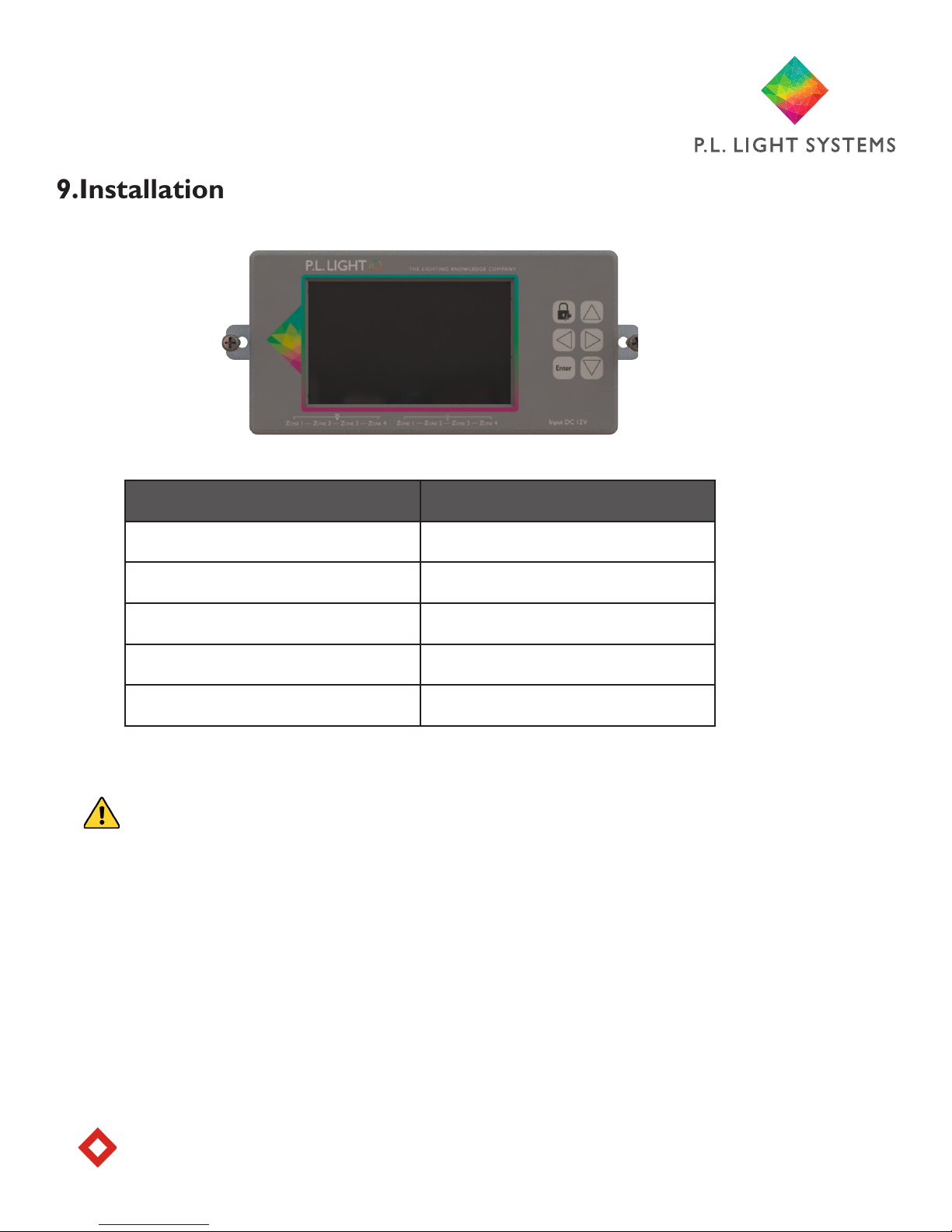
Tools and Parts Required Task
2x Screws Mounting controller to wall
2x Anchors (optional) Mounting controller to wall
Drill Mounting controller to wall
Screwdriver Mounting controller to wall
RJ12 Crimp Tool (optional) Modifying cable length
1. Determine the optimal location for the controller. Heed warnings in Section 5.
Caution! The P.L. Light iQ™ controller should only be mounted on a sturdy, solid surface.
2. Holding the controller in desired location, mark the position of the holes on the
mounting surface, using the mounting tabs (on either side of the controller).
3. Set controller aside and drill holes in marked locations from step 2. Insert anchors
into holes if required.
4. Position controller against mounting surface—mounting tabs should be aligned with
drilled holes. Insert one screw into each hole and tighten with a screwdriver until con-
troller is securely attached to the mounting surface.
Note: Ensure not to over tighten to avoid breaking the mounting tabs.
9.Installation

Page 10
Zone Zone Zone Zone
1 2 3 4
Port A
Luminaires
(RJ12 connector)
SD
Card
Port C
5V DC
Input
10. Inputs
Zone Zone Zone Zone
1 2 3 4
Port B
Temperature Sensors
(RJ12 connector)
11. Connecting To Luminaires
Refer to section11: Connecting to Luminaires below.
1. Once the controller is securely mounted, insert one end of the supplied RJ12 cable into the relevant
Zone (1–4) Port A on the control unit.
2. Insert the other end of the RJ12 cable into the RJ port on the luminaire or RJ12 T-splitter (not sup-
plied) if connecting more than one luminaire in a zone.
Note: If the cable length of the temperature sensor cable is insufcient to reach the controller, the
cable can be lengthened with an RJ12 (6 pin / 6 position) cable and a RJ12 (6 pin / 6 position) straight
through inline coupler.
3. Plug the RJ12 connector from the temperature sensor into the corresponding Zone (1–4) tempera-
ture Port B on the bottom panel of the controller and run the sensor cable the full length up to and
across the ceiling if possible. The sensor should be positioned as close as possible to the center of the
grow space within each zone. Repeat using additional temperature sensors (not supplied) for remaining
zones.
Caution! Take care not to stress or damage the sensor cables when securing them to walls or ceilings.
Note: Ensure the sensor is shielded from the light, as this may disrupt temperature measurements. Use
a hood if necessary. Template is located on page 21 and in the Quick Start Guide.
4. Once all connections have been made to the controller, plug the supplied Power Supply (see part “c”
on page 7) into a power outlet and connect the other end to the power input Port C on the bottom
panel of the controller and proceed to initial setup.
5. Finally, connect the luminaires to the power source (120 – 240V).
Note: Luminaires cannot be boosted when using 120V supply.
You are now ready to setup and program the controller. Proceed to initial setup.
Tabla de contenidos


