Pericom Company Confidential
Pericom Semiconductor Corp.
www.pericom.com
Page 4 of 4 4/29/2013
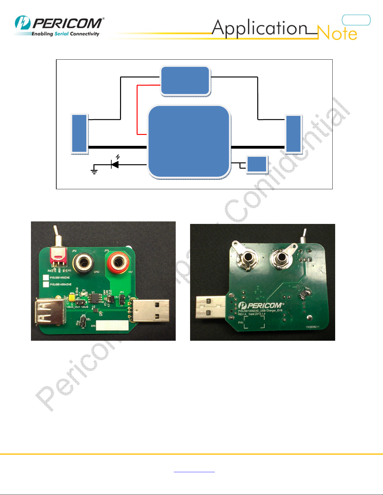
Detail Description
The functionality of header pins, switch are detail described in this section.
Functionality of Header Pins & Banana Jack
Header
Pin
Remark
JP1
Pin 1 = PI5PD2068 output
Pin 2 = Vbus pin of USB
receptacle connector
Pin 1 = PI5PD2069 output
Pin 2 = Vbus pin of USB
receptacle connector
Short = connect the +5V output to
USB receptacle connector
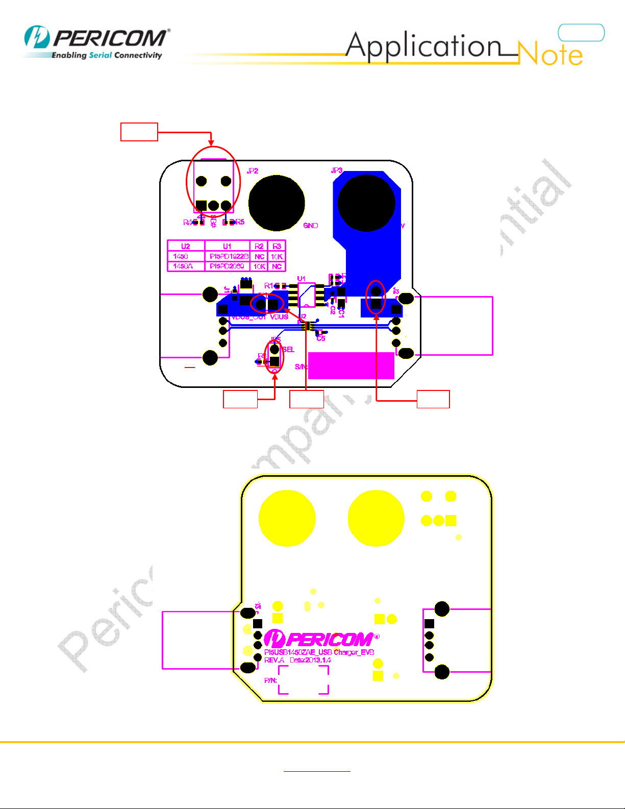
JP4 Pin 1 = Vbus from USB plug
Pin 2 = VDD of PI5USB1458
Pin 1 = Vbus from USB plug
Pin 2 = VDD of PI5USB1458A
Short =EVB power up by Vbus of
USB plug
Open = EVB need to power up by
external power supply
JP5 Pin 1 = 10kohm to +5V
Pin 2 = SEL of PI5USB1458
Pin 1 = 10kohm to +5V
Pin 2 = SEL of PI5USB1458A
Short →SEL = high
Open →SEL = Low
Jack PI5USB1458 PI5USB1458A Remark
JP2 GND GND If use external power support, JP4
must be Open
JP3 +5V from external power
support
+5V from external power
support
Functionality of Switches
Switch
PI5USB1458/
PI5USB1458A
Description
SW1 SB#
Configure Mode,
0 (LEFT side) = Sleep and charge mode,
1 (RIGHT side) = Normal USB mode
Switches and header pin Setting
SEL Feature
SW1
0 0 Auto Sleep & Charge - with keyboard/mouse pass through
1
1 0
1
0 charging with CDP / SDP (depends on external device)
LEFT side =
Sleep and
charge mode
RIGHT side =
USB mode