Northern Telecom DMS-100 Series Manual de funcionamiento
BCS33 and up Standard 02.01 December 1991
297-2101-504
DMS-100 Family
PCM30 Line Drawer
Maintenance Guide


PCM30 Line Drawer
Maintenance Guide
BCS33 and up
DMS-100 Family
PCM30 Line Drawer
Maintenance Guide
1991 Northern Telecom
All rights reserved.
Printed in Canada and printed in the United States of America.
Information is subject to change without notice. Northern Telecom reserves the right to make changes in design or components
as progress in engineering and manufacturing may warrant.
DMS
,
DMS SuperNode
,
MAP, and
NT are trademarks of Northern Telecom.
Publication number: 297-2101-504
Product release: BCS33 and up
Document release: Standard 02.01
Date: December 1991

297-2101-504 Standard 02.01 December 1991
ii
Publication history
December 1991
BCS33 Standard 02.01 incorporate dual-tone multifrequency (DTMF)
outpulsing
January 1991 BCS31 Standard 01.02 first release of this document

PCM30 Line Drawer
Maintenance Guide
BCS33 and up
iii
Contents
About this document v
When to use this document v
How to identify the software in your office v
How PCM30 Line Drawer documentation is organized vi
References in this document vi
What precautionary messages mean vii
How commands, parameters, and responses are represented viii
Understanding the PCM30 line drawer 1-1
Application of the PCM30 line drawer 1-2
Example of a PCM30 line drawer application 1-2
System configuration 1-5
How the PCM30 line drawer is configured 1-6
How the peripheral modules are configured 1-8
PCM30 line drawer maintenance 2-1
PCM30 line drawer maintenance description 2-2
Fault detection and isolation 2-2
Performing maintenance functions 2-3
Clearing drawer faults 3-1
PM LCM 3-2
minor 3-2
Card replacement procedures 4-1
NT6X27CA 4-2
PCM30 line drawer 4-2
NT6X54CA 4-4
PCM30 line drawer 4-4
List of terms 5-1

iv Contents
297-2101-504 Standard 02.01 December 1991
List of figures
Figure 1-1 Provision of exchange lines from a host LCM 1-3
Figure 1-2 Provision of exchange lines from a PRLCM 1-4
Figure 1-3 PLD and DMS configuration 1-5
Figure 1-4 PCM30 line drawer 1-7
Figure 1-5 LCA shelf layout 1-9
Figure 1-6 LCE frame layout 1-11
Figure 1-7 PRLCM frame layout 1-12
List of procedures
Replacing an NT6X27CA in a PLD 4-2
Replacing an NT6X54CA in a PLD 4-4
List of tables
Table 2-1 PLD drawer states 2-2

PCM30 Line Drawer
Maintenance Guide
BCS33 and up
v
About this document
This document describes the maintenance of the PCM30 line drawer (PLD).
Procedures are provided for clearing alarms and replacing cards. This docu-
ment is intended for maintenance personnel in an operating company.
When to use this document
Northern Telecom (NT) software releases are referred to as batch change
supplements (BCS) and are identified by a number, for example, BCS29.
This document is written for DMS-100 Family offices that have software
loads of BCS33 and up.
More than one version of this document may exist. The version and issue
are indicated throughout the document, for example, 01.01. The first two
digits increase by one each time the document content is changed to support
new BCS-related developments. For example, the first release of a
document is 01.01, and the next release of the document in a subsequent
BCS is 02.01. The second two digits increase by one each time a document
is revised and rereleased for the same BCS.
To determine which version of this document applies to the BCS in your
office, check the release information in DMS-100 Family Guide to Northern
Telecom Publications, 297-1001-001.
How to identify the software in your office
The Office Feature Record (D190) lists your current BCS and the NT
feature packages in it. You can view similar information on a MAP
(maintenance and administration position) terminal by typing
>PATCHER;INFORM LIST;LEAVE
and pressing the Enter key.
vi About this document
297-2101-504 Standard 02.01 December 1991
How PCM30 Line Drawer documentation is organized
This document is part of PCM30 Line Drawer (PLD) documentation that
supports the Northern Telecom line of PLD products. PLD documentation
is a subset of the DMS-100 Family library.
PCM30 Line Drawer documentation consists of the following documents.
Number Title
297-2101-114
PCM30 Line Drawer Planning, Engineering, and Administration
Guide
Provides an introduction to the PLD, as well as planning,
engineering, and administration information.
297-2101-504
PCM30 Line Drawer Maintenance Guide
Provides a set of procedures for maintaining the PLD, including
clearing alarms, replacing cards, and performing routine
procedures.
The DMS-100 Family library is structured in numbered layers, and each
layer is associated with an NT product. To understand PCM30 Line Drawer
products, you need documents from the following layers:
•DMS-100 Family basic documents in the 297-1001 layer
•PCM30 Line Drawer documents in the 297-2101 layer
References in this document
The following documents are referred to in this document.
Number Title
297-1001-103
Peripheral Modules Manual
297-1001-558
Peripheral Module Alarm Analysis and Card Replacement
Procedures Manual
297-2101-516
Line Maintenance Reference Manual
About this document vii
PCM30 Line Drawer
Maintenance Guide
BCS33 and up
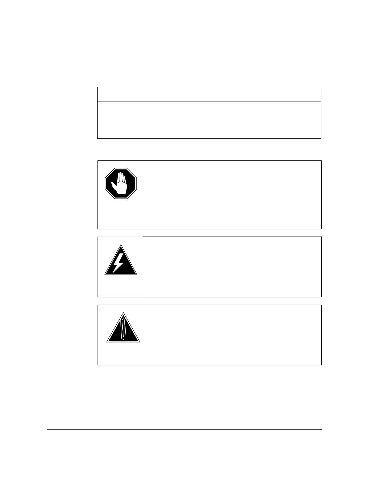
What precautionary messages mean
Danger, warning, and caution messages in this document indicate potential
risks. These messages and their meanings are listed in the following chart.
Message Significance
DANGER Possibility of personal injury
WARNING Possibility of equipment damage
CAUTION Possibility of service interruption or degradation
Examples of the precautionary messages follow.
DANGER
Risk of electrocution
The inverter contains high voltage lines. Do not open the front
panel of the inverter unless fuses F1, F2, and F3 have been
removed first. Until these fuses are removed, the high voltage
lines inside the inverter are active, and you risk being
electrocuted.
WARNING
Damage to backplane connector pins
Use light thumb pressure to align the card with the connectors.
Next, use the levers to seat the card into the connectors. Failure
to align the card first may result in bending of the backplane
connector pins.
CAUTION
Loss of service
Subscriber service is lost if you accidentally remove a card from
the active unit of the peripheral module (PM). Before
continuing, confirm that you are removing the card from the
inactive unit of the PM.
viii About this document
297-2101-504 Standard 02.01 December 1991
How commands, parameters, and responses are represented
Commands, parameters, and responses in this document conform to the
following conventions.
Input prompt (>)
An input prompt (>) indicates that the information that follows it is a
command:
>BSY
Commands and fixed parameters
Commands and fixed parameters that are entered at a MAP are shown in
uppercase letters:
>BSY LINK
Variables
Variables are shown in lowercase letters:
>BSY LINK ps_link
The letters or numbers that the variable represents must be entered. Each
variable is explained in a list that follows the command string.
Responses
Responses correspond to the MAP display and are shown in a different type:
Any active calls may be lost
Please confirm (“YES” or “NO”):
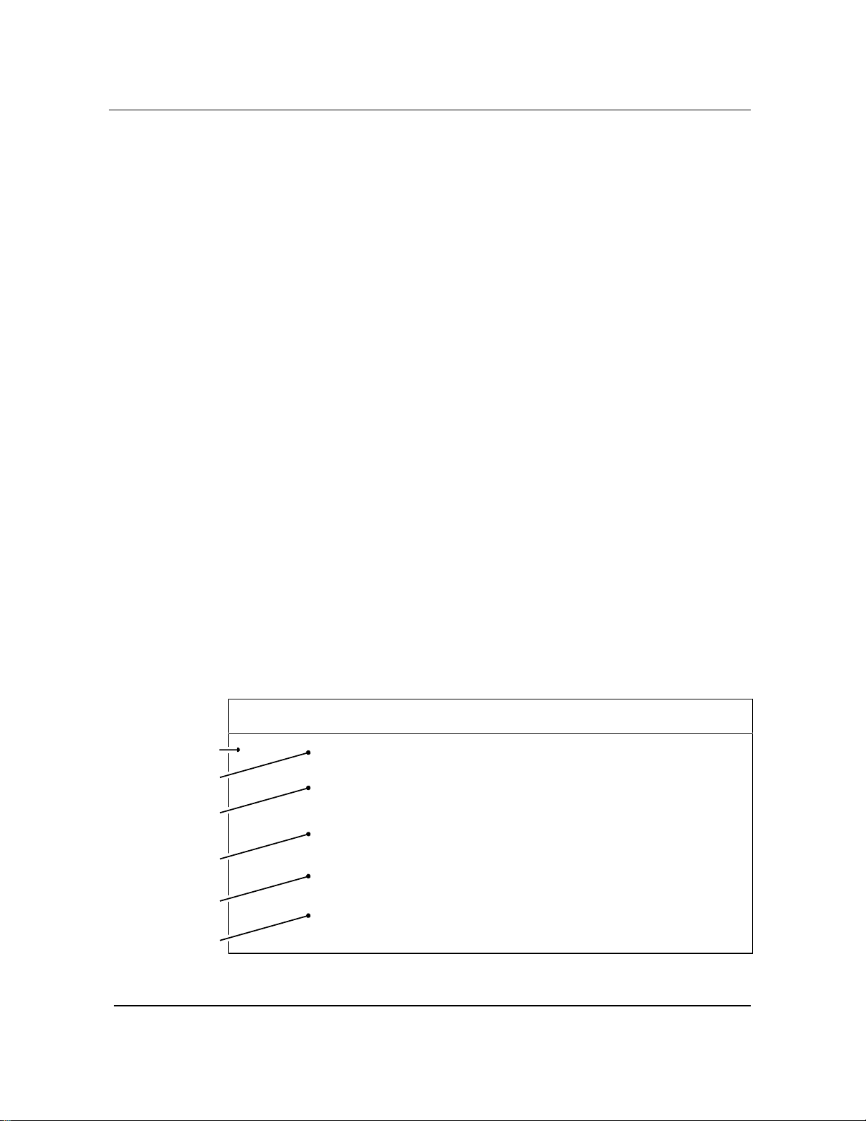
The following example illustrates the command syntax used in this
document.
Step Action
1Busy the P-side link of the SMU by typing
>BSY LINK ps_link
and pressing the Enter key.
where
ps_link is the number of the P-side link (0 through 19)
Example input:
>BSY LINK 7
Example of a MAP response:
Any active calls may be lost
Please confirm (“YES” or “NO”):
Step number
Instruction
Command
input
Parameters
list
Example
input
Example
output
Otros manuales para DMS-100 Series
9
Este manual sirve para los siguientes modelos
1
Tabla de contenidos
Otros manuales de Sistema telefónico de Northern Telecom


