Northern Lights GEM Series Manual de usuario

www.northern-lights.com
M944T3F
GEM Series Sound Enclosure
Assembly Instructions
000 COVER PAGE

Corporate Headquarters
4420 14th Avenue NW
Seattle, WA 98107
Tel: (206) 789-3880
Fax: (206) 782-5455
Southeastern U.S.A.
1419 W Newport Center Dr
Deereld Beach, FL 33442
Tel: (954) 421-1717
Fax: (954) 421-1712
Alaska Branch Ofce
1200 West International
Airport Road
Anchorage, AK 99519
Tel: (907) 562-2222
Fax: (907) 563-1921
East Coast Branch
15 Aegean Dr.
Suite 4
Methuen MA 01844
Tel: (978) 475-7400
Fax: (978) 475-7745
Gulf Branch
19 Veterans Memorial Blvd.
Kenner, LA 70062
Tel: (504) 360-2180
Toll Free: (800) 843-6140
Northern Lights
4420 14th Avenue NW
Seattle, WA 98107
Tel: (206) 789-3880
Fax: (206) 782-5455
Copyright ©2019 Northern Lights, Inc.
All rights reserved. Northern Lights™, and
the Northern Lights logo are trademarks of
Northern Lights, Inc.
Printed in U.S.A.
LIT NO.: L818 5/19

ITEM # DESCRIPTION ADE P/N QTY NOTES
1. 1/4” NPT x 3-1/2” pipe nipple 21-01208 1
2. 3/8” NPT x 3” pipe nipple 21-01207 1
3. 1/4” NPT brass pipe cap 21-72241 1
4. 3/8” NPT brass pipe cap 21-78004 1
5. Rear intake duct assembly 06-71272 1
6. M8 button head hex screw 12-00118 10
7. 5/16” ext tooth lockwasher 15-09204 16
8. 5/16” pan head machine screw 12-00119 6
9. Rear panel/valence assembly 06-71202 1 includes 06-71269
10. Hole plug 1” white 00-78006 6
11. 1/4”-20 pan head machine screw 12-45102 12
12. 1/4” ext tooth lockwasher 15-09103 12
13. Service side lower valence 06-71206 1
14. Non-service side lower valence 06-71207 1
15. Sound foam, side valence 55-71261 2
16. Front lower valence assembly 06-71213 1
17. Service side panel aft 06-71209 1
18. Non-service side panel aft 06-71212 1
19. Non-service side panel fwd 06-71211 1
20. Front panel assembly 06-71201 1
21. Seal bar 06-71271 1
22. Service side panel fwd assembly 06-71208 1
23. Top panel aft assembly 06-71204 1
24. Top panel fwd assembly 06-71203 1
25. Grommet, vented loop 00-70146 2 optional use
SPECIFICATIONS
Enclosure:
Length (OA) 60.1 in (1527 mm)
Width 29 in (737 mm)
Height 32.1 in (815 mm)
Assembled height on base frame: 32.1 in (815 mm)
Assembled weight w/o sub-base (est): 164 lbs (74 kg)
M944T3F GEM Sound Enclosure
1
Prior to assembly, inspect all components for damage. Report any damage to the shipping company. Check the packing list in the back of this manual
to be sure all parts are included.
Select a mounting location in accordance with the guidelines in the IM1000 Installation Manual. The generator set must typically be mounted on a
rigid, at surface above a strong structure, such as the vessel’s stringers, to minimize vibration transference to the hull.
Note that the generator set is designed for single side service. When viewed from the rear, the left hand side is the service side and should be exposed
for easy maintenance access.
Install the generator set in the vessel as near to a level attitude as possible. Ensure that the enclosure’s right hand side and rear are at the
recommended distances (6 inch recommended, 4 inch minimum.) from the vessel’s bulkheads.
A
Note: The Generator set may still possess original factory lifting points. These lifting points will need to be loosened and rotated down, below the highest
point of the engine. Be sure to tighten these bolts before installing generator set.
AVOID POSITIONING THE ENCLOSURE INTO CORNERS WITH OVERHEAD BLOCKED TO REDUCE CHANCE OF INTAKE/EXHAUST AIR
RECIRCULATION OUTSIDE THE SHIELD.
A
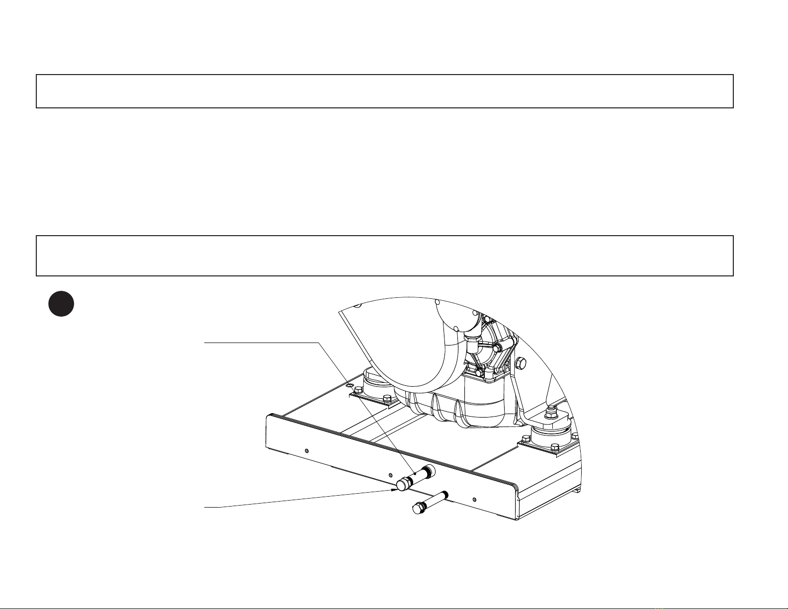
IN FRONT OF BASE FRAME.
(items #1 and 2.)
STEP 1.
INSTALL PIPE NIPPLES TO
CORRESPONDING SIZE PORTS
STEP 2.
INSTALL PIPE CAPS (items 3 and 4.)
TO PIPE NIPPLES.
VIEW: FRONT OF GENSET BASE FRAME
PAGE 2 GRAPHIC
2

3
A
DETAIL A
SCALE 1 : 4
STEP 3.
LOCATE AND INSTALL REAR LOWER INTAKE DUCT
ASSEMBLY (item 5.) TO TAPPED HOLES AT REAR OF BASE FRAME.
STEP 4.
INSTALL 4x BUTTON HEAD HEX SCREW AND 4x STARWASHER (items 6 AND 7.)
TO SECURE DUCT ASSEMBLY TO BASE FRAME USING 5mm HEX TOOL.
VIEW: REAR OF GENSET BASE FRAME.
SOUND FOAM OMITTED
FOR VIEW CLARITY.
B
PAGE 3 GRAPHIC
A
DETAIL A
SCALE 1 : 4
STEP 5.
INSTALL REAR PANEL/LOWER
VALENCE ASSEMBLY (item 9.)
TO REAR OF GENSET/BASE FRAME.
6x 5/16" EXTERNAL STARWASHER (item 7.)
6x 5/16" PAN HEAD MACHINE SCREW (item 8.)
VIEW: RIGHT CORNER AFT
F
DETAIL F
SCALE 1 : 4
VIEW: LEFT SIDE CORNER AFT
5/16" PAN HEAD MACHINE SCREW (item 8.)
5/16" EXTERNAL STARWASHER (item 7.)
PAGE 3 LOWER GRAPHIC
C
B
C

DETAIL A
E
STEP 8.
INSTALL NON-SERVICE SIDE LOWER VALENCE (item 14.)
USING 1/4"-20 PAN HEAD MACHINE SCREW AND 1/4" STARWASHER
(items 11 and 12.) SEE INSET DETAIL, TYPICAL BOTH SIDES.
STEP 9.
INSTALL SERVICE SIDE LOWER VALENCE (item 13.)
USING 1/4"-20 PAN HEAD MACHINE SCREW AND
1/4" STARWASHER (items 11 and 12.)
INSET DETAIL A
3X 1/4"-20 PAN HEAD MACHINE
SCREW (item 11.) EACH SIDE.
3x 1/4" STARWASHER (item 12.)
EACH SIDE
PAGE 4 LOWER GRAPHIC
A
DETAIL A
SCALE 1 : 4
D
VIEW: BOTTOM REAR OF SOUND SHIELD
STEP 6.
SECURE REAR LOWER VALENCE PANEL TO REAR OF
BASE FRAME WITH 3x BUTTON HEAD HEX SCREW (item 6.) AND
3x STARWASHER (item 7.) USING 5mm HEX TOOL.
STEP 7.
WHEN REAR PANEL/LOWER VALENCE ASSEMBLY IS SECURED
INSERT HOLE PLUGS (item 10.)
PAGE 4 GRAPHIC
D
E
4

STEP 10
INSTALL FRONT LOWER VALENCE ASSEMBLY (item 16.)
A
DETAIL A
VIEW: FRONT
3x BUTTON HEAD HEX SCREW (item 6.)
AND 3x STARWASHER (item 7.)
STEP 11
INSTALL 3x HOLE PLUGS (item 10.) WHEN
FRONT VALENCE (item 16) IS SECURED.
DETAIL B
FOLLOWING COMPLETION OF
FRONT VALENCE INSTALL SIDE
VALENCE SOUND FOAM (item 15.)
TYPICAL EACH SIDE.
DETAIL DETAIL B
SCALE 1 : 4
3x 1/4" STARWASHER
(ITEM 12.) EACH SIDE.
3x 1/4"-20 PAN HEAD
MACHINE SCREW
(item 11.) EACH SIDE.
INSET DETAIL B
F
PAGE 5 GRAPHIC
F
5

G
A
E
G
B
F
D
C
VIEW: REAR
G
PAGE 6 GRAPHIC
For keel cooled
application.
STEP 12
CONNECT GENERATOR SET TO THE VESSEL. SEE PICTURE BELOW AND LEGEND.
a. Connect the exhaust elbow of the diesel engine to the exhaust system of the vessel. Pass the three inch exhaust hose through the opening provided in the
right side of the rear panel.
b. Connect the sea water pump to the vessel’s water inlet. Pass a 3/4” ID hose from the vessel’s sea water strainer, through the bottom hole on the right side
of the rear panel to the sea water pump inlet tting.
c. Connect the vessel’s fuel supply and fuel return to the generator set using Coast Guard approved rubber fuel hose. Fuel connections are 5/16-37T JIC inlet
and 1/4-37T JIC outlet located at the fuel manifold on the base frame of the generator set’s left hand side, through the bottom hole in the left side of the rear
panel.
d. Connect the DC control panel harness to the genset engine harness plug through the middle hole on the rear panel’s left lower side.
e. Connect the 12 volt battery leads to the generator set using the top slot on the right side of the rear panel.
f. Connect the AC output leads from the generator junction box to the vessel’s power distribution panel. Pass the two leads through the top slot on the left side
of the panel.
g. *OPTIONAL* This port is used for water outlet in Keel Cooled applications.
Install connections for exhaust, AC power
leads, DC control panel leads, battery and
water inlet through holes in the rear panel
as shown in the drawing and as described
below:
A
6

7
C
STEP 13
INSTALL SERVICE SIDE PANEL AFT (item 17.)
DETAIL C
CAPTIVE SCREWS.
FINGER START AND WITH FINISH LIGHT HAND TIGHT
USING PHILLIPS HEAD SCREW DRIVER.
DO NOT OVER TIGHTEN.
STEP 14
INSTALL NON-SERVICE SIDE PANEL
AFT (item 18.) SEE DETAIL C.
H
PAGE 7 GRAPHIC
H

I
D
STEP 15
INSTALL NON SERVICE SIDE PANEL FWD (item 19.)
SEE DETAIL D.
DETAIL D
CAPTIVE SCREWS.
FINGER START AND FINISH LIGHT HAND TIGHT
USING PHILLIPS HEAD SCREW DRIVER.
DO NOT OVER TIGHTEN
.
I
PAGE 8 GRAPHIC
8
Otros manuales para GEM Series
3
Este manual sirve para los siguientes modelos
1
Tabla de contenidos
Otros manuales de Recinto de Northern Lights


 Manual de usuario")


