OSCBR225-EN
10/13
INSTALLATION, OPERATION & MAINTENANCE INSTRUCTIONS
HANDLING & STORAGE
HANDLING
Do not drop or throw the product as it may break.
STORAGE
Store away from dust, moisture and direct sunlight.
If possible, store in the original package.
CHECKING
• Check the product code, power supply, and voltage
before installation.
• Make sure that the bolts are not loose.
• The DIP switch should be set up before the power is
turned on. Do not touch unnecessary switches.
(PAX)
INSTALLATION
PRECAUTIONS
• Flush the pipeline carefully before installing the
valve. Foreign particles, such as sand or pieces of
welding electrode, will damage the ball and seats.
• For valves with specified flow direction (GS / VR) or
with ST / SC option, check the arrows on the product
before piping.
PIPING FLANGES
• Gasket should be selected appropriately to suit the
fluid, pressure and temperature.
Use spring washer to prevent from decreasing
surface pressure gasket when the temperature
change happens frequently.
• Tighten all bolts using crossover method to load the
joint evenly.
• Wafer type ball valve is put between two seats of
flanged-end and tightened with long bolts. (BS / GS)
ENVIRONMENT
• Do not install in place where corrosive gas is present
or where vibration is heavy (0.5 G or more).
• When radiant heat causes the surface temperature
of the control unit to exceed 55 °C, provide an
appropriate shielding plate.
• If there is a possibility that the fluid and drive part
freeze, please take measures to prevent freezing.
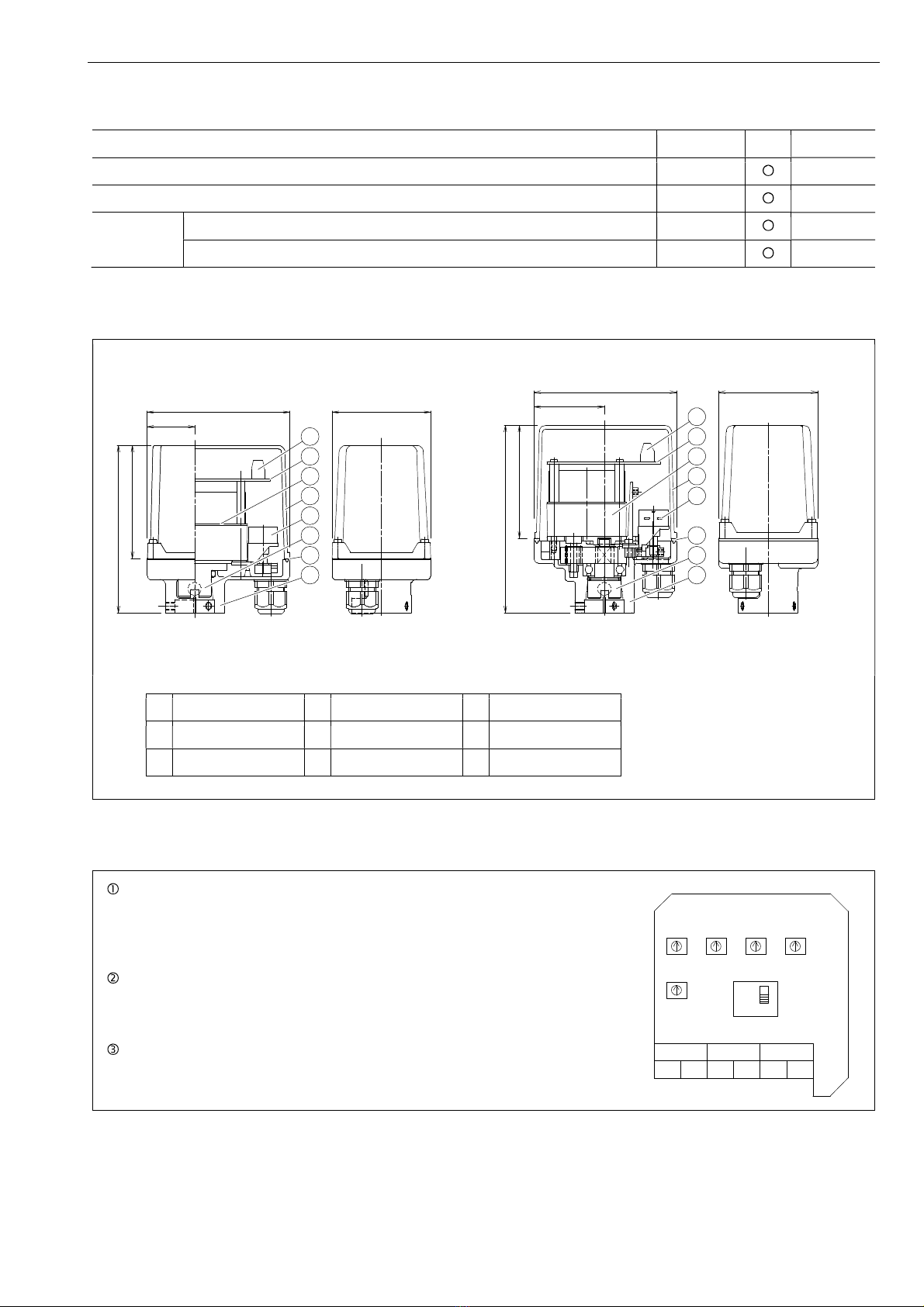
POSITIONING
Should be positioned through 90° upward from
horizontal. Provide space around the product to
allow manual operation, inspection and replacement
work.
Margin required around the actuator for maintenance
AM (030 / 070) DM2 (030) More than 65 mm
AM AH1 DM PAX More than 90 mm
OTHER NOTES
Until the wiring is completed there must be no
condensation or flooding in the interior of the
actuator, after piping. Protective caps on the cable
gland are not waterproof.
CAUTIONS FOR MAINTENANCE (GS)
Do not keep warm for maintenance of the valve
gland.
TIGHTEN THE GLAND NUTS (GS)
• Check that there is no leakage from the gland
packing.
• If it leakage, tighten gland nuts by alternately.
Do not over-tighten the gland nuts.
Recommended torques
Valve size [mm]
Torque [Nm]
GS
V-port Full port Standard port
015
020
015
020 - 2
025
032
025
032 040 3.5
WIRING
• Do not wiring outdoors on a rainy day.
• Check the power supply and voltage.
Connect the signal as shown in the wiring diagram.
• Do not connect unnecessarily terminal.
• Use suitable flexible cable (5 to 10.5 mm).
Lock and seal the cable completely to prevent
condensation inside the actuator.
• Built-in terminal block can clamp up to 1.5 mm in
diameter without using solderless terminal.
• Allow proper cable slack for maintenance.
• Actuator should be electrically grounded.
Use the terminal marked ( ) inside the actuator.
PREVENT DEW CONDENSATION
• When installing the cover after wiring, perform the
bolt by the temporary tightening procedure and the
permanent tightening procedure to tightly and
securely tighten the rubber packing so that water
does not enter from the outside.
• Tighten the cable gland nut so that there is no
leakage from the wire entrance.
Gland nut
Gland plate
Stem