nilan Compact P Manual de usuario

INSTALLATION INSTRUCTIONS
Compact P / Compact P Polar
CTS602 HMI BY NILAN
Version 5.00 - 01.08.2023
M24 Compact P GB

2
Table of contents
General information
Important information ......................................................................................................................................................................... 4
Safety ............................................................................................................................................................................................................ 4
Power supply ......................................................................................................................................................................................... 4
Heat pump domestic hot water ......................................................................................................................................................... 4
Water quality requirements ...................................................................................................................................................................... 4
Requirements to quality of water ..................................................................................................................................................... 4
Introduction .................................................................................................................................................................................................. 5
Documentation ..................................................................................................................................................................................... 5
Unit type ....................................................................................................................................................................................................... 6
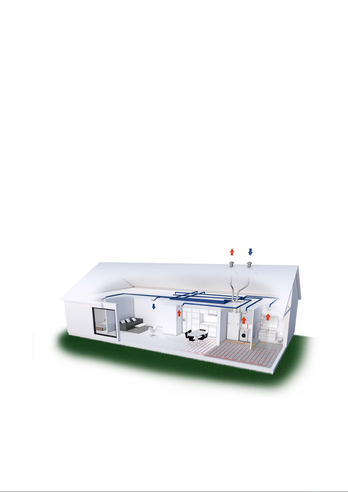
Product description .............................................................................................................................................................................. 6
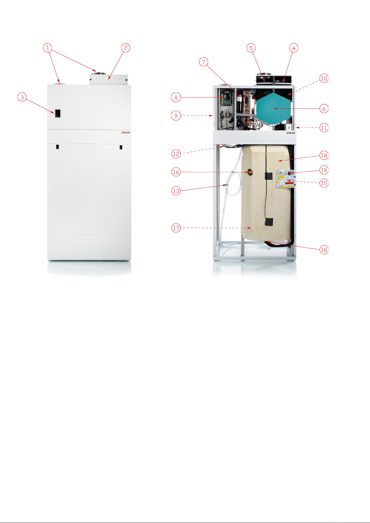
The unit ................................................................................................................................................................................................... 7
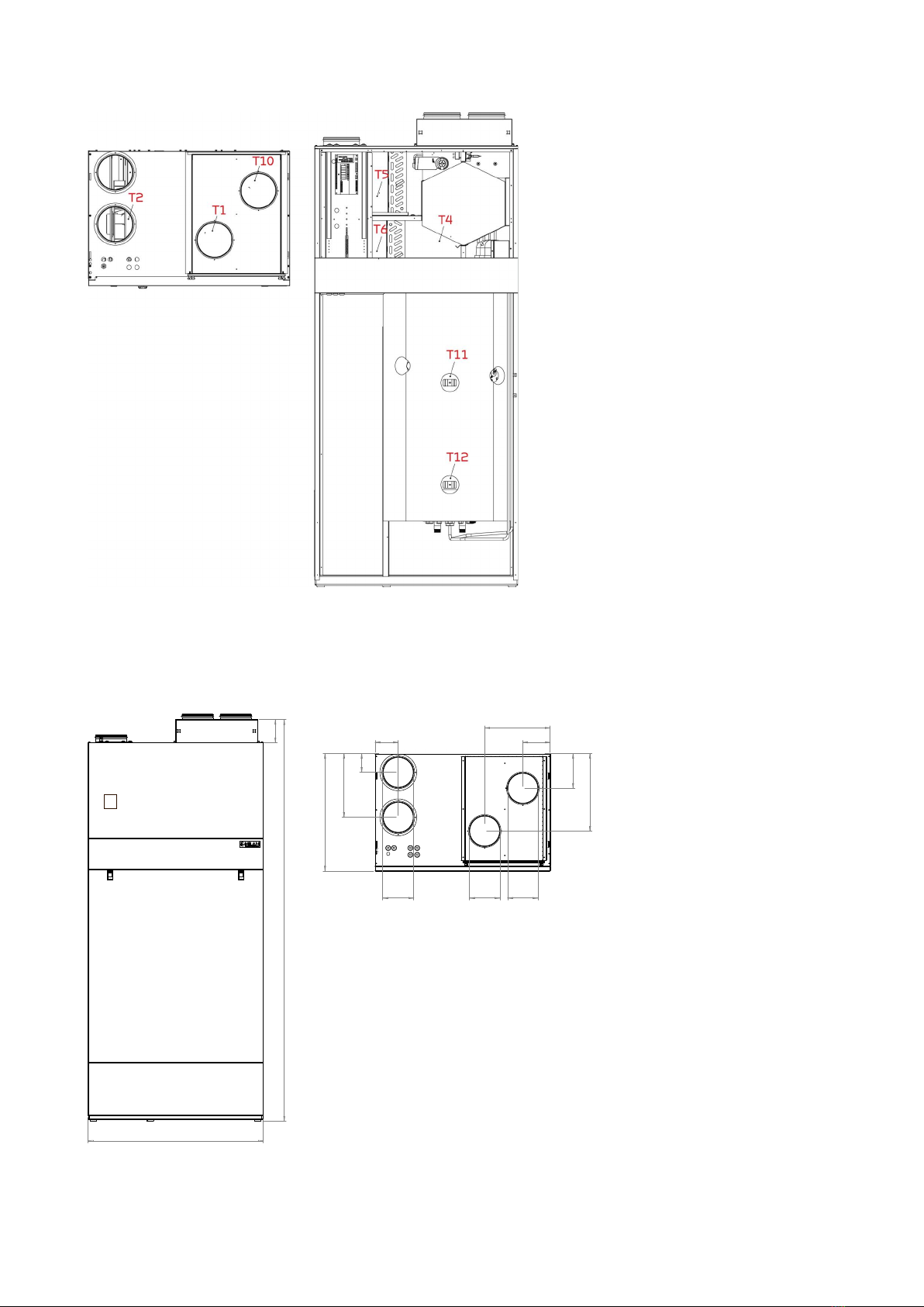
Temperature sensor overview .......................................................................................................................................................... 8
Dimensional drawing ............................................................................................................................................................................ 8
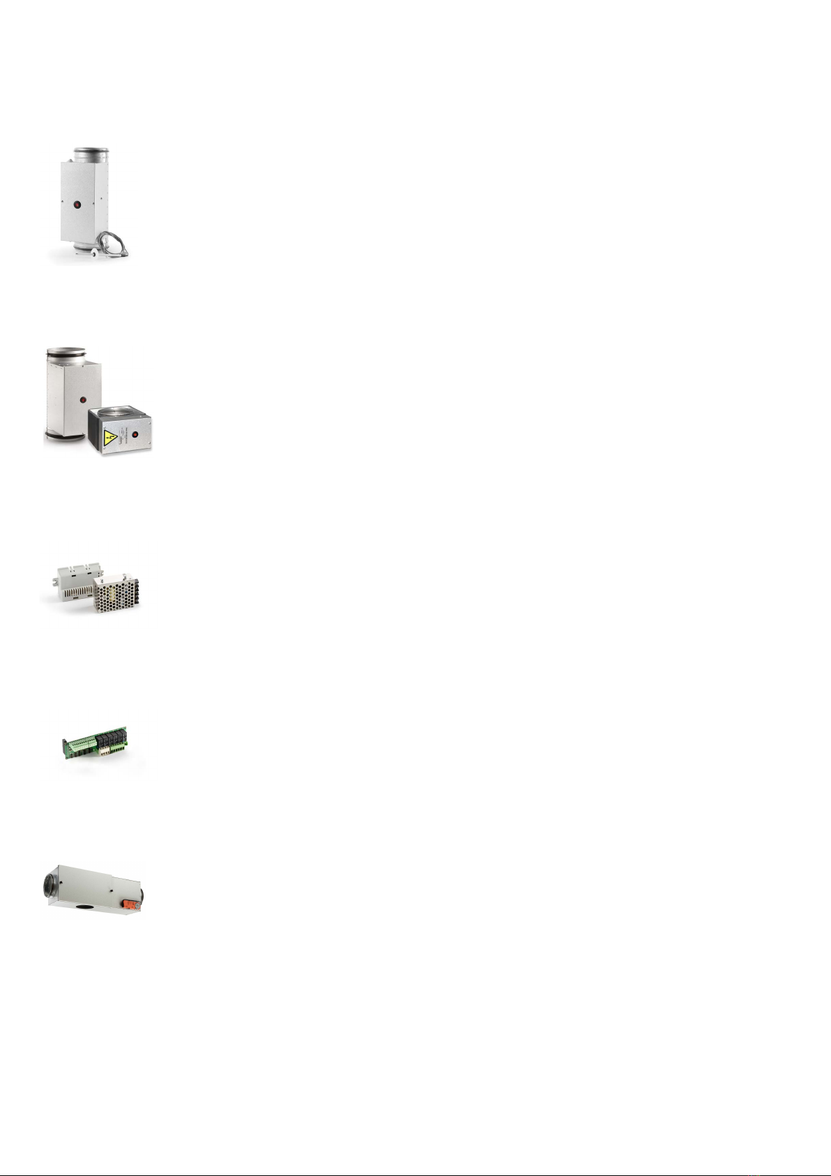
Accessories .................................................................................................................................................................................................. 9
Electrical pre-heating element for frost protection of the unit ................................................................................................... 9
Electrical after-heating element for duct installation ................................................................................................................... 9
CO2 sensor ............................................................................................................................................................................................. 9
Expansion PCB ....................................................................................................................................................................................... 9
EM-box .................................................................................................................................................................................................... 9
DTBU damper ......................................................................................................................................................................................10
Extension cable HMI control panel ..................................................................................................................................................10
Cover plate HMI user panel ...............................................................................................................................................................10
Safety group ........................................................................................................................................................................................10
Safety group with scalding protection ...........................................................................................................................................10
Flexible sound damper .......................................................................................................................................................................11
Pollen filter ...........................................................................................................................................................................................11
Trolley ...................................................................................................................................................................................................11
Gateway with App option ..................................................................................................................................................................11
Set-up
Mounting .....................................................................................................................................................................................................12
Transport into the building ...............................................................................................................................................................12
Positioning the unit ............................................................................................................................................................................12
Electrical installation
Safety ...................................................................................................................................................................................................13
Connections overview ......................................................................................................................................................................13
Electrical connection unit ........................................................................................................................................................................13
Power supply .......................................................................................................................................................................................13
HMI Control panel ......................................................................................................................................................................................14
Moving the control panel ..................................................................................................................................................................14
Wall bracket .........................................................................................................................................................................................14
Electrical connection accessories ..........................................................................................................................................................15
User selection 1 ..................................................................................................................................................................................15
Modbus .................................................................................................................................................................................................15
External electrical pre-heating element ........................................................................................................................................16
Electrical after-heating element .....................................................................................................................................................17
CO2 sensor ...........................................................................................................................................................................................18
Installation of expansion PCB on CTS602 circuit board ..............................................................................................................20
User selection 2 ..................................................................................................................................................................................21
EM-box (damper option) ....................................................................................................................................................................21
DTBU (damper option) .......................................................................................................................................................................22
Fire thermostat / external fire automation system ....................................................................................................................23
Joint alarm ............................................................................................................................................................................................23
External heat supply ..........................................................................................................................................................................24
Plumbing installation
Condensate drain ......................................................................................................................................................................................25
Important information .......................................................................................................................................................................25
Hot water tank ...........................................................................................................................................................................................26
Connection overview .........................................................................................................................................................................26
Connection ...........................................................................................................................................................................................26
Requirements to quality of water ...................................................................................................................................................27
Hot water circulation .........................................................................................................................................................................27
Supplementary coil ............................................................................................................................................................................27
Softened water ...................................................................................................................................................................................27
Plumbing connections accessories ........................................................................................................................................................28
Safety group ........................................................................................................................................................................................28

3
Safety group with anti-scald protection ....................................................................................................................................... 28
Ventilation installation
Duct system ............................................................................................................................................................................................... 29
Legislation ........................................................................................................................................................................................... 29
Ducts .................................................................................................................................................................................................... 29
Ventilation unit ................................................................................................................................................................................... 29
Extract air ............................................................................................................................................................................................ 30
Supply air ............................................................................................................................................................................................. 30
Roof terminals .................................................................................................................................................................................... 30
Installation example .......................................................................................................................................................................... 30
Balancing .................................................................................................................................................................................................... 31
Important information ...................................................................................................................................................................... 31
Troubleshooting
Emergency mode ...................................................................................................................................................................................... 32
Emergency mode domestic hot water ........................................................................................................................................... 32
Domestic hot water .................................................................................................................................................................................. 33
Errors and solutions domestic hot water ...................................................................................................................................... 33

4
General information
Important information
Safety
Power supply
Heat pump domestic hot water
The heat pump must undergo suitable service inspections under applicable legislation and regulations to keep it in good condition and
in compliance with safety and environmental requirements.
Responsibility for maintenance of the heat pump rests with the owner/user.
Water quality requirements
Requirements to quality of water
The hot water tank in the Nilan units is made of steel, which has been given a double enamelling, to ensure an extra long service life. In
addition, the tank is equipped with a sacrificial anode as extra protection. It is important that the sacrificial anode is replaced regularly.
Most units are equipped with an electronic monitoring sacrificial anode, which gives an alarm on the user panel when it is time to re-
place it.
In order for the sacrificial anode to function and protect the tank, it is required that the water quality complies with the following:
• Electrical conductivity (EC): Between 30 mS/m and 150 mS/m (millisiemens pr. m) @ 25 °C
• Chloride must be below 250 mg/L @ 65 °C
If the above criteria are not met, the sacrificial anode will not work as intended, after which the tank will be corroded.
CAUTION
Do not turn on the power supply for the unit until the hot-water tank and central heating circuit is filled with water.
CAUTION
Always disconnect the power supply to the unit if an error occurs that cannot be rectified via the control panel.
CAUTION
If an error occurs on electrically conductive parts of the unit, alway contact an authorised electrician to rectify the error.
CAUTION
Always disconnect the power to supply to the unit before opening the unit doors, for instance for installation, inspection,
cleaning and filter change.
CAUTION
Avoid direct contact with the heating system pipes in the heat pump as they can get very hot.
CAUTION
To protect the heat pump against damage, it is equipped with electronic temperature monitoring.

5
Introduction
Documentation
The following documents will be supplied with the unit:
• Quick guide
• Wiring diagram
In the Quick guide you will find important information regarding installation and start-up of the unit. If you require further information
regarding, for instance, installation of accessories or additional settings in the software, or if you need an extended user manual, the
following documents can be downloaded from the Nilan website:
• Installation instructions
• Software instructions
• User Manual
• Wiring diagram
The instructions can be downloaded from www.nilan.dk.
If you have questions regarding installation and operation of the unit after having read the instructions, please contact your nearest
Nilan dealer. A list of Nilan dealers is available on www.nilan.dk.
From factory, the unit has been tested and is ready for operation.
ATTENTION
The unit must be started up immediately after installation and connection to the duct system.
When the ventilation unit is not in operation, humidity from the rooms will enter the duct system and create condensate
water that can run out of the valves and cause damage to floors and furniture. Condensation may also form in the ven-
tilation unit, which can damage its electronics and fans.

6
Unit type
Product description
Compact P is a ventilation unit with heat recovery, that has a built-in heat pump, which is used for the production of domestic hot wa-
ter, but which is able to heat and cool the home via the ventilation air.
Compact P is designed for air flows of up to 275 m3/h at 100 Pa external counter-pressure.
The unit is primarily used in residential construction such as single-family houses and apartments. It ventilates the home by drawing
out the moist and bad air via valves in e.g. bathrooms, toilet, kitchen and utility room, and introduces fresh outdoor air in via valves in
living rooms such as. living room, bedrooms and family room.
The cold outdoor air is heated via the high-efficiency counterflow heat exchanger by the hot exhaust air. The heat loss that occurs via
heat recovery, the built-in heat pump use to produce domestic hot water. All the energy in the exhaust air is utilized, and you have not
really seen any heat loss that you experience with an ordinary ventilation unit.
In the winter, the built-in heat pump can heat the supply air up to 34 ° C, and thus contribute to heating the home. When the supply air
is heated, at the same time a little heat is deposited in the hot water tank and ensures a constant high hot water temperature.
The heat pump has a reversible cooling circuit, which means that the cooling circuit can be turned and it can cool the supply air in the
summer. Compact P can cool the supply air by up to 10 ° C in relation to the outdoor air. Due to the low air exchange, usually 1/2 time
per hour, it will not act as an air conditioning system. However, when cooling, moisture in the supply air is removed, which results in a
lower humidity in the home. The lower humidity means that it is easier to withstand a slightly higher temperature, which therefore pro-
vides good comfort in the home.
When Compact P cools the supply air, the energy is deposited in the hot water tank, and it can thus be said that “free” domestic hot wa-
ter is produced during those periods.

7
The unit
1. Duct connections
2. Filter change cover
3. Control panel (HMI touch-panel)
4. Extract air filter
5. Outdoor air filter (pollen filter is placed here if required)
6. Counterflow heat exchanger
7. Heat pump
8. Automation CTS602
9. Fans
10. 100% bypass damper
11. Pre-heating element for frost protection (Polar version
only)
12. USB-cable (for connecting to PC)
13. Condensate drain with water trap
14. 180 l hot water tank
15. 1,5 kW electrical supplement heater (with overheat protec-
tion)
16. Electronically monitored sacrificial anode
17. Supplementary coil (only SOL version)
18. Plumbing connections
19. Emergency mode (domestic hot water)

8
Temperature sensor overview
Dimensional drawing
Temperature sensors inside the unit
T1: Outdoor air
T2: Supply air
T4: Extract air after heat exchanger
T5: Condenser
T6: Evaporator
T10: Extract air
Temperature sensors outside the unit
T7: Supply air after heating element
(accessory)
Temperature sensors in the hot water tank
T11: Top of tank
T12: Bottom of tank
Connections:
1. Outdoor air
2. Supply air
3. Extract air
4. Discharge air
Weight: 213 kg.
All listed measurements are in mm.
900
2065 120
1
2
3
4
160
97
328
610
179
399
141
337
160160
119

9
Accessories
Electrical pre-heating element for frost protection of the unit
Electrical after-heating element for duct installation
CO2 sensor
Expansion PCB
EM-box
If your ventilation unit is not a Polar version with an integral pre-heating element, we recommend that you
purchase an external pre-heating element as frost protection of the ventilation unit.
During prolonged periods of frost, the high efficiency counterflow heat exchanger will ice up. To prevent ice
formation, we recommend that you install an electrical pre-heating element.
The pre-heating element consumes limited energy and it ensures efficient heat recovery without periods of
defrosting the counterflow heat exchanger. You thereby achieve an overall reduction in energy consump-
tion.
Installing an after-heating element allows you to control the supply air temperature in the following cases:
• You want to use the ventilation air to heat the dwelling
• You want to control the supply air temperature to avoid potential cold draughts and coldness from the
ventilation
The electrical after-heating element is for installation in the supply air duct. It would be an advantage to
place it within the climate screen. It comes with the necessary sensors and connectors.
If you want to adjust the fan speed level in accordance with the level of use of the dwelling/building (amount
of people), you can retrofit a CO2 sensor. Nilan’s CO2 sensors calibrate automatically.
On the control panel, you select the CO2 level you want. If this level is exceeded, ventilation will automatically
increase.
An expansion PCB extends the functions in the control system so you can control various accessories.
Under “Electrical connection accessories” you will be able to see which accessories require an expansion PCB.
If you want to run the cooker hood via the ventilation unit, in some cases there may be insufficient air for
cooker hood extraction.
If you install an EM-box, you can regulate the extracted air when the cooker hood is in operation, so that less
air is drawn from, for instance, the bathroom and the utility room. This will allow enough air for the cooker
hood to extract sufficiently.
The EM-box is fitted with a metal filter that cleans the air in the cooker hood of grease particles efficiently. It
thereby protects the ventilation unit.

10
DTBU damper
Extension cable HMI control panel
Cover plate HMI user panel
Safety group
Safety group with scalding protection
If there is insufficient space for mounting an EM-box in the installation, you can achieve the same effect by
controlling the extract air with a DTBU damper.
You then have to adjust the duct system yourself with a connection to the cooker hood.
The control panel for the ventilation unit is connected up with a short wire so it can be installed close to the
unit.
If you place the unit so the control panel is out of sight, for instance in a cupboard or in the loft, you can order
a 15 m extension cable with plug. This allows you to place the control panel where it is visible to the user.
It is important that the control panel is visible so the user can see alarms when, for example, filters need
replacing.
It is possible to move the HMI control panel away from the unit and place it in a more visible place.
A cover plate can be ordered to cover the hole where the control panel was located.
By law, a safety group must be fitted for the cold water connection to the hot water tank.
Nilan offers a safety valve in brass with the following functions:
• Safety valve
• Check valve
• Stop valve
• Drain tab
The control has a software scald protection that ensures that the water in the hot water tank does not gets
too hot.
If you have a large cooling and / or heating need, it may be necessary to deactivate the software scald pro-
tection. The water in the hot water tank can be up to 90 ° C, which is why you need to install a safety group
with scald protection.
If a solar panel is used to heat the domestic hot water via the supplementary coil in the hot water tank, a safe-
ty group with scald protection must be fitted.
Otros manuales para Compact P
9
Este manual sirve para los siguientes modelos
2
Tabla de contenidos
Manuales populares de Sistema de agua de otras marcas

Spirotech
Spirotech SPIROVENT SUPERIOR S250 Manual de usuario

Culligan
Culligan Aqua-Cleer Aqua-Cleer Advanced Drinking Water... Manual de usuario

A.O. Smith
A.O. Smith Dura-Max AJH - 1000A - P Manual de usuario

Microline
Microline T.F.C.-4 Manual

Eureka Forbes
Eureka Forbes Aquaguard Select Manual de usuario

Cetetherm
Cetetherm AquaEfficiency Manual de usuario


