Night Watcher NW1201X Instrucciones de instalación

1
Motion tracking
sensor led light
Installation & operating manual
NIGHTWATCHER surveillance pro
Model no
nw1201X

2
Table of contents
1. Contents of package
2. Nightwatcher Surveillance Pro L.E.D
3. Installation
4. Programming your Surveillance Pro
5. Set the date and time of Surveillance Pro
6. iewing video
7. Technical Specifications
8. General Information and Safety
Contents of packaging
Nightwatcher Surveillance Pro
User Manual
1 Allen key
Accessory bag: 2pcs screws, 2pcs plastic masonry plugs
Micro SD and SD adaptor
Nightwatcher
Surveillance Pro
Micro SD Card &
SD adaptor
User Manual Allen Key
Screws Plastic Masonry plugs

3
INTRODUCTION
Congratulations on the purchase of your new Nightwatcher Security Light. Before installation of
the unit, please read the operating instructions and safeguards carefully. It is important that you
read and follow the instructions in the manual, even if you feel you are familiar with this type of
product.
Please retain the instructions in a safe place for future reference
SPECIFICATIONS
Model Number:
NW1200x
AC Input:
220-240 50Hz
Time Adjustment:
Fixed at 3 Minutes
Sensor Range:
10m x 210°
Power Consumption:
8 Watts
IP eather Rating:
IP55
Light Source:
8 x 1Watt Nichia High Power L.E.D
Camera (Video):
20 seconds image recording for image stream:
10fps at 480x640 Pixels – A I format
Camera (Photo)
640 x 480 – JPEG format
Camera Viewing
Distance – 8M, Angle – 60 Degree
Motor Life
20,000 revolutions
IMPORTANT SAFEGUARDS
HEN USING ELECTRICAL APPLIANCES, IN ORDER TO REDUCE THE RISK OF FIRE,
ELECTRIC SHOCK, AND/OR INJURY, THESE BASIC SAFETY PRECAUTIONS SHOULD
AL AYS BE FOLLO ED:
General information and SAFETY
Read all instructions carefully, even if you feel you are quite familiar with the appliance.
• Any alterations or additions to building wiring, must be completed by a licensed electrical
mechanic, or person authorised by legislation to work on the fixed wiring of any electrical
installation
• To prevent electric shock, please ensure that power is disconnected before installing.
• The appliance is not intended for use by children or infirm persons without supervision.
• Children should be supervised to ensure that they do not play with the appliance.
• This unit must be connected to a 220-240 50Hz power source
• The light must be earthed
• The cable installed shall be 3 x 1.0mm² at least
• The unit is for outdoor use only
• The unit is for wall mounting
• The NW Surveillance Pro is designed to be weather resistant. Never attempt to immerse the unit in
water or any other liquid. This will damage the unit and void the warranty.
• This product is designed to illuminate, video, and make verbal announcements. It will not prevent
the commission of any act, legal or illegal. The manufacturer assumes no liability for any damage
to property, injury to person, or death.
COMPULSORY WARNING
Note: No user serviceable parts inside. Unauthorised modification voids warranty, Return to place of
purchase for replacement or service under warranty.
SAVE THESE INSTRUCTIONS

4
OVERVIEW
Camera
3 motion sensors
Mode LED Indicator
(hidden inside)
LED
TIME/DATE SET
OFF/REC
RESET
Mode push-button
Speaker
AUDIO MODE
SET/REC PLAY/ERASE
MIC
LCD
Waterproofed cover
LED indicator
Side view
Left 70
Right 70
0
25
Camera adjustable
down 25
°
°°
°

5
Step 1. Insert/remove Micro SD card (see fig. 1)
When the Surveillance Pro is powered, press the push-button on the bottom of the unit for 3
seconds to stop the light turning before attempting to insert or remove the Micro SD card. To
resume operation, push the push-button again.
Unscrew the waterproofed cover using provided Allen key, and then insert the Micro SD
card until it automatically locks into place.
If you need to remove the Micro SD card, please press OFF/REC button and take it out
within 30 seconds.
When LED light turns green, this means the Micro SD card is being read, do not remove
SD card or data may be lost.
To remove Micro SD card, push in Micro SD card to eject then pull out.
Step 2. Installation
IMPORTANT
IF IN ANY DOUBT ABOUT THE INSTALLATION OF THIS PRODUCT, CONSULT A QUALIFIED ELECTRICIAN
- This product must be grounded
- Do not mount the unit against inflammable surfaces
- The motion detector will not operate correctly if it is installed:
1 Near the outlet of a central heating boiler
2 Near air conditioning plant
3 Pointing directly at moving vehicles
4 Within sight of reflections from moving water
5 Where other lamps could shine on the detector
*BEFORE ATTEMPTING ANY INSTALLATION OR MAINTENANCE, ENSURE THAT THE
ELECTRICAL SUPPLY IS SWITCHED OFF AND THE CIRCUIT FUSES REMO ED OR THE
CIRCUIT BREAKER IS IN THE OFF POSITION.
*Please make sure the voltage and polarity are correct before connection. Incorrect voltage may cause
electric shock. If you are not sure, please contact your retailer.
* DO NOT REMOVE THE TAPE UNTIL YOU FINISH THE INSTALLATION. IF THE TAPE COMES OFF
THE LIGHT, PLEASE REPLAE IT OR HOLD THE LIGHT HEAD TO AVOID S IVELING AND
DAMAGE THE PRODUCT.
*Note: It is recommend to mount Smart Tracker 2M above the ground for optimum performance, do not
mount the fixture below 1.2M. See below figure for details of performance range.
Fig. 4
Fig. 2
LED light
Micro SD card slot
Fig. 1
TOP IEW
GOOD
SENSITI ITY LESS SENSITI ITY

6
Detection range: 10M x 210°
°°
° (see fig. 3)
Installing your UNIT onto a surface.
(See fig. 4 & fig. 5)
1. Place plastic masonry plugs into desired surface aligning holes as shown below. Using an
electric screwdriver, fasten mounting plate directly to surface using screws E.
2. Feed the cable through the back mounting box and bush the cable entry to avoid abrasion to
the cable.
3. Wire the unit as follows: (Ensure all wires are connected securely and that no loose strands
are exposed)
4. Make sure the polarity is correct. Double check the connections after wiring. Mis-wiring may
damage the motion sensor or cause a fire hazard.
5. Place plastic masonry plugs into desired surface aligning holes as shown below. Using an
electric screwdriver, fasten mounting plate directly to surface using screws
Fig. 4
Fig. 3
Fig. 4

7
Please allow 1 minute warm-up time after switching on.
* Push the RESET button after switching on.
Remove plastic lens cover from camera and the tape after installation. (See fig. 6)
Step 3. Adjusting the Settings
(see fig. 7~10)
Selecting working mode: Mode LED Indicator hidden inside the lens will display
different LED lights when switching different modes. LED light will turn off after 30
seconds.
Mode 1: Perfect for a place of business (default setting)
Light at night + camera all day + speaker at night
-Daytime: light is off, camera is on, speaker is off
-Nighttime: light is on, camera is on, speaker is on
Mode 2: Suggested setting when out of town
Light + camera + speaker: all day detection
-Daytime and nighttime: light, camera and speaker are all in operation
Mode 3: Suggested for day to day use
Light at night + camera all day + speaker in the daytime
-Daytime: light is off, camera is on, speaker is on
-Nighttime: light is on, camera is on, speaker is off
* For above 3 modes, after audio is triggered, no audio will be triggered in the following
30 seconds.
Fig. 6
Fig. 5
Mode LED Indicator
(hidden inside the lens)
Sy bol
Mode 1 RED
Mode 2 ORANGE
Mode 3 GREEN
this
Fig. 7

8
this
Camera LED for indicating the function status of the unit by different color LED lights.
1) Red: Micro SD card (part no.②) is not inserted into the Micro SD slot or the system is
malfunctioning.
2) Green: The unit is recording.
3) LED off: stand by Micro SD card is inserted into the slot), when OFF/REC button is
pressed.
* Before removing Micro SD card from the slot, please press the push-button on the
bottom of the Smart Tracker for 3 seconds to stop the light turning. To resume to work,
push the push-button again.
* Please note when OFF/REC button is pressed, remove Micro SD card (part no.②)
within 30 seconds (now the LED will turn red after Micro SD card is removed from the
slot)
Reset button: restore functions to default settings
1) Press RESET button once each time you turn on unit.
2) Please press this button in case of system malfunction.
Off/Rec:Please press OFF/REC button to remove Micro SD card. Please remove card
within 30 seconds of pressing the OFF/REC button to avoid loss of data.
Audio mode: for selecting which audio message will play when motion sensor detects
movement.
- Pre-set default is “silent mode”
- Push one time for “doorbell chime”
- Push again for “dog barking”
- Push one more time for the message you recorded (Message 1)
- Push again for additional message you recorded (Message 2 - you can record up to 2
messages at a time)
Step 4. Recording Audio Messages (see fig. 10)
1. Press the SET/REC button for 3 seconds, and you will hear a single beep. After the beep,
start recording your message by talking into the microphone (see fig. 10). Push the button
again to stop recording, and you will hear a series of 2 beeps, meaning the recording is
finished. If you do not push the button again after you have recorded the message, the
recording will stop automatically after 10 seconds.
2. Smart Tracker can hold 2 self-recorded messages. If you have recorded one message,
repeat above step for message 2.
2. If you hear a series of 3 beeps when you want to record your message by pressing
the SET/REC button for 3 seconds, this means the self-recorded messages are full,
please erase previous messages.
Fig. 8
Fig. 10
TIME/DATE SET
OFF/REC
RESET
Fig. 9
PLAY/ERASE

9
LCD
TIME/DATE SET
OFF/REC
Play/Erase : allows you to listen to and erase messages (see fig. 10)
i. If you have only recorded 1 message, push the button one time to listen to
recorded Message 1. If you wish to erase it, press the PLAY/ERASE button and hold it
for 3 seconds. You will hear a series of 2 beeps, indicating the message has been
erased.
ii. If you have recorded 2 messages, push the button one time to listen to the first
message, and push it again to listen to the second message. If you want to erase a
message, select that message, and after listening to it, push the
PLAY/ERASE button and hold it for 3 seconds to erase it.
iii. If message 1 is erased, message 2 will automatically become message 1.
The next message you record will then become the new message 2.
Step 5. Set the Data and Time:
This will allow the security video taken by N Surveillance Pro to display the correct date
and time it was taken.
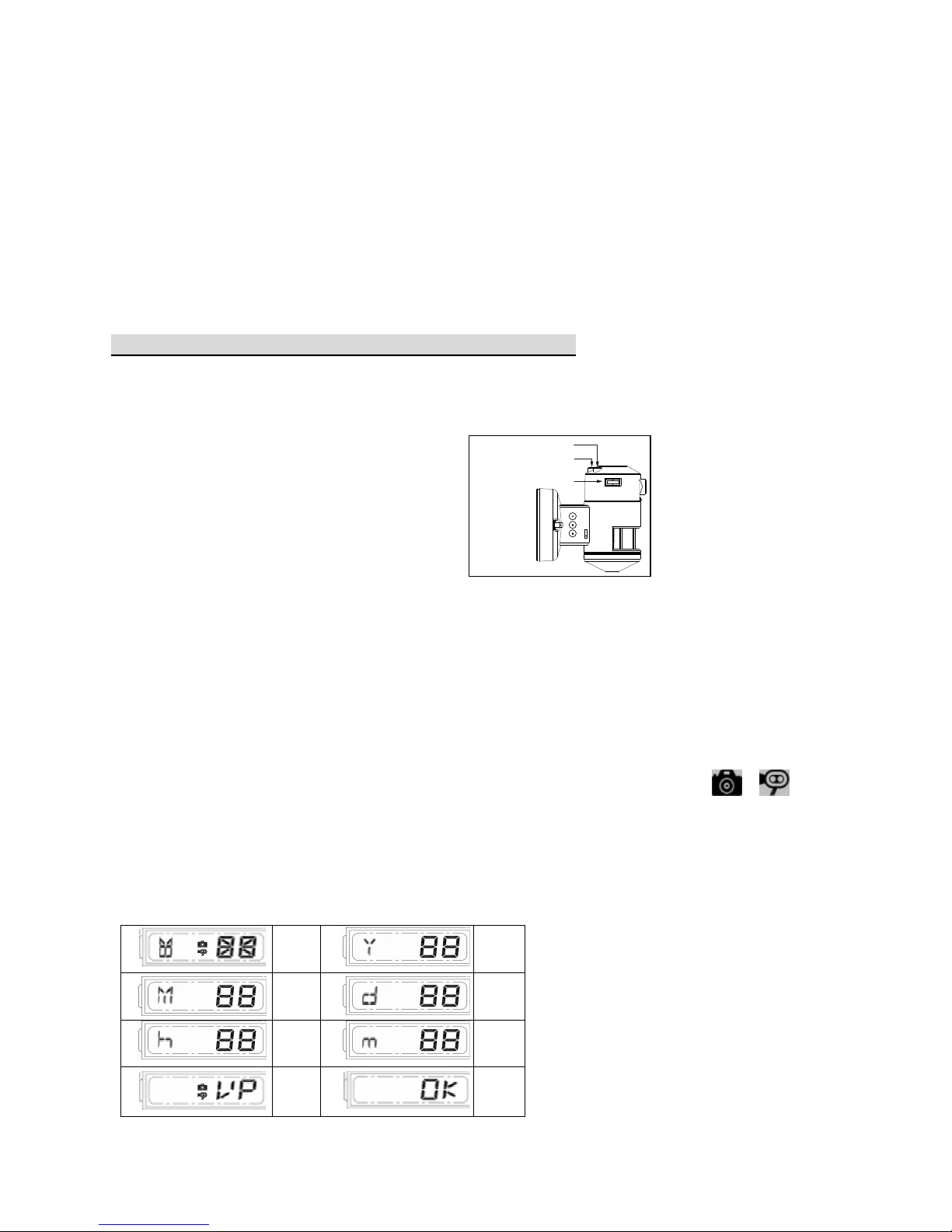
1. Push TIME/DATE SET button (see fig. 11) for 3 seconds, LCD screen will flash 3 times
indicating you have entered Time/Date setting mode.
1. “YEAR “setting:
::
:”Y” and “08” displayed on the screen;push the button to set year from“08-
99”, push the button again and hold for 3 seconds to scroll through numbers quickly. If you
have not pressed the button for 3 seconds, it will automatically save the year and go on to
allow you to set the month.
2. Repeat the same setting procedure for
MONTH/DATE/HOUR/MINUTE.
1.
“VIDEO/PHOTO ”setting:
::
:
when entering this mode, these two icon
and “ ” appear on the screen push the button to choose” ”(ideo or”P”(Photo).
If you have not pushed any buttons for 3 second, “OK” will appear on the screen, indicating it
has automatically saved the current settings. The LCD screen will shut off automatically 10
seconds later.
* On the”P” (photo) setting, Smart Tracker will take a series of digital photographs at a rate of 3
photos every second when the motion sensor is triggered
①
Start
②
YEAR
Setting
③
MONTH
Setting
④
DATE
Setting
⑤
HOUR
Setting
⑥
MINUTE
Setting
⑦
VIDEO/
PHOTO
Setting
⑧
Finish
Fig. 11

10
Step 6. Viewing video
1. Viewing image by computer through a card reader (see fig. 12)
Open the waterproofed cover on the NW Surveillance Pro.
Press OFF/REC button and remove Micro SD card from the slot.
Put the Micro SD card into adapter then insert this adapter into card reader. Connect PC
and card reader by USB cable (not included) and open any media player to view the
video.
Special care instructions
The NW Surveillance Pro is designed to be weather resistant. Never attempt to immerse the
unit in water or any other liquid. This will damage the unit and void the warranty.
This product is designed to illuminate, video, and make verbal announcements. It will not
prevent the commission of any act, legal or illegal. The manufacturer assumes no liability for
any damage to property, injury to person, or death.
Use a soft lens cloth for cleaning lens. Avoid touching lens with fingers.
Remove dirt or stains with a soft cloth dampened with water or neutral detergent. Keep the
NW Surveillance Pro in a dry and cool dust-free environment or container when it is NOT
used
Do not open the NW Surveillance Pro for unauthorized service. This could cause serious
damage to the unit and will void the warranty.
This NW Surveillance Pro is a precision electronic device. Do not attempt to service this
camera yourself, as opening or removing covers may expose you to the danger of electric
shock or other risks.
Fig. 12
Tabla de contenidos
Otros manuales de Sistema de seguridad de Night Watcher
Manuales populares de Sistema de seguridad de otras marcas

EDM
EDM Solution 6+6 Wireless-AE Manual de usuario

Highway Safety Group
Highway Safety Group EA401 Manual de usuario

Siren
Siren LED GSM Manual de usuario

Detection Systems
Detection Systems 7090i Instrucciones de montaje

Se-Kure Controls
Se-Kure Controls MicroMini SK-4841 Manual de usuario

Siemens
Siemens FDM273 Manual de usuario