NGX Technologies BlueBoard-LPC11U24 Manual de usuario

Quick Start Guide: BlueBoard-LPC11U24/37
1www.ngxtechnologies.com
BlueBoard-LPC11U24/37
Fig. 1
User Manuals for BlueBoard-LPC11U24/37:
For KEIL MDK-ARM with ULINK2: Click here
For LPC-Xpresso with NXP-LPC-Link: Click here
Sample projects for BlueBoard-LPC11U24:
For KEIL MDK-ARM: Click here
For LPC-Xpresso: Click here
Sample projects for BlueBoard-LPC11U37:
For KEIL MDK-ARM: Click here
For LPC-Xpresso: Click here
Schematic for BlueBoard-LPC11U24:
Click here to download Schematic.
Schematic for BlueBoard-LPC11U37:
Click here to download Schematic.

Quick Start Guide: BlueBoard-LPC11U24/37
2www.ngxtechnologies.com
About NGX Technologies
NGX Technologies is a premier supplier of development tools for the ARM7, ARM Cortex M0, M3 and
M4 series of microcontrollers. NGX provides innovative and cost effective design solutions for
embedded systems. We specialize in ARM MCU portfolio, which includes ARM7, Cortex-M3, M0 &
M4 microcontrollers. Our experience with developing evaluation platforms for NXP controller enables
us to provide solutions with shortened development time thereby ensuring reduced time to market and
lower development costs for our customers. Our cost effective and feature rich development tool
offering, serves as a testimony for our expertise, cost effectiveness and quality.
Contact Information:
NGX Technologies Pvt. Ltd.
No.216, 5th main Road, R.P.C. Layout,
Vijayanagar 2nd Stage,
Bangalore –560 104
Phone : +91-80-40925507
email:[email protected]
CE certification
NGX Technologies BLUEBOARD-LPC11U24/37 board have been tested for radiated emission as per
EN55022 class A standard. The device is under the limits of the standard EN55022 class A and hence
CE marked. No other test have been conducted other than the radiated emission (EN55022 class A
standard). The device was tested with the ports like USB, Serial, and Power excluding the GPIO ports.
Any external connection made to the GPIO ports may alter the EMC behaviour. Usage of this device
under domestic environment may cause unwanted interference with other electronic equipment’s. User
is expected to take adequate measures. The device is not intended to be used in and end product or any
subsystem unless the user re-evaluates applicable directive/conformance.

Quick Start Guide: BlueBoard-LPC11U24/37
3www.ngxtechnologies.com
Table of Contents
1.0 INTRODUCTION.................................................................................................................................4
1.1 Possible Debuggers and IDEs that can be used.................................................................................4
1.2 ULINK2 and KEIL............................................................................................................................4
1.3 NXP-LPCLink and LPCXpresso.......................................................................................................5
1.4 NGX CoLinkEx and Coocox CoIDE................................................................................................5
2.0 BLUEBOARD-LPC11U24/37 OVERVIEW........................................................................................7
2.1 INTRODUCTION.............................................................................................................................7
2.2 Board Features...................................................................................................................................7
2.3 Block Diagram ..................................................................................................................................8
2.4 MCU Features ...................................................................................................................................8
3.0 BLUEBOARD-LPC11U24/37 Hardware Description .......................................................................10
3.1 Introduction .....................................................................................................................................10
3.2 Board Image with pointer to each peripheral & connectors............................................................10
4.0 BLUEBOARD-LPC11U24/37 hardware verification.........................................................................11
4.1 Board connections...........................................................................................................................11
4.2 Powering the Board.........................................................................................................................12
4.3 Verifying all the peripherals on Blueboard.....................................................................................12
4.3.1 LEDs.............................................................................................................................................12
4.3.2 Buzzer...........................................................................................................................................13
4.3.3 Graphics LCD (GLCD)................................................................................................................13
4.3.4 RTC..............................................................................................................................................13
4.3.5 Micro SD Card .............................................................................................................................13
4.3.6 ADC..............................................................................................................................................14
4.3.7 PS/2 Keyboard..............................................................................................................................14
4.3.8 USB..............................................................................................................................................14
4.3.9 UART...........................................................................................................................................15
4.3.9 External Interrupt Switch & Wakeup Switch...............................................................................16
5.0 CHANGE HISTORY..........................................................................................................................17
5.1 Change History................................................................................................................................17
6.0 REFERENCES....................................................................................................................................17

Quick Start Guide: BlueBoard-LPC11U24/37
4www.ngxtechnologies.com
1.0 INTRODUCTION
This document is the Quick Start Guide for the BLUEBOARD-LPC11U24/37, a low cost ARM Cortex-
M0 based board by NGX Technologies. This document reflects its contents which include MCU
features, board features and hardware verification and possible debuggers and IDEs that can be used
with this board.
1.1 Possible Debuggers and IDEs that can be used
ULINK2 with KEIL uVision
NXP LPCLink with LPCXpresso
NGX CoLinkEx with Coocox CoIDE
Red Probe+ with Red Suite from Code Red
I-jet with IAR Embedded Workbench
Segger JLink with IAR Embedded Workbench or KEIL uVision
1.2 ULINK2 and KEIL
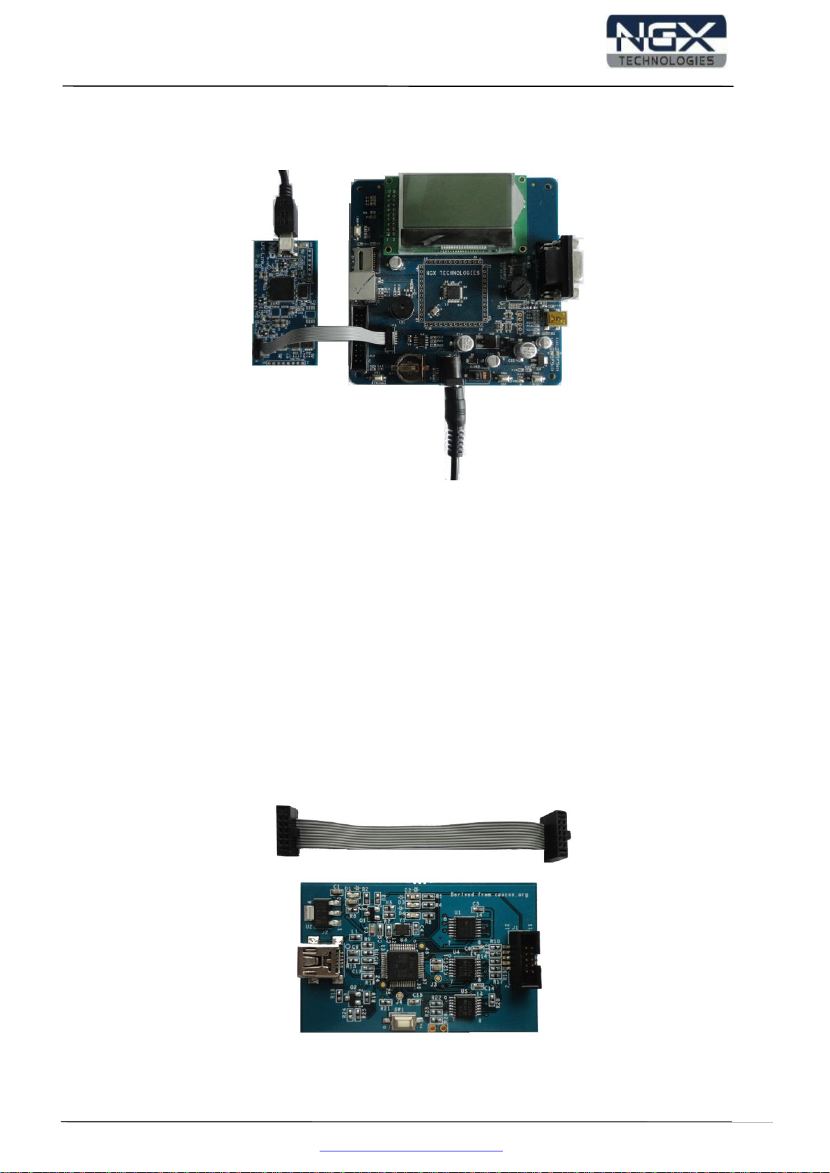
Connect the ULINK2 20-pin cable to 20-pin connector on the board, connect USB cable to the ULINK2
and connect the power supply to the board as shown in the below image. The hardware setup is now
ready for programing a BLUEBOARD-LPC11U24/37 board with ULINK2 and KEIL IDE.
Note: ULINK2 is not a part of the BLUEBOARD-LPC11U24/37package, User need to buy separately.
Fig. 2

Quick Start Guide: BlueBoard-LPC11U24/37
5www.ngxtechnologies.com
1.3 NXP-LPCLink and LPCXpresso
Separate the LPCXpresso controller part and use only the NXP LPC-Link as shown in the below image.
Fig. 3
The BLUEBOARD-LPC11U24/37 board has on board Cortex SWD/JTAG 10-pin box, the one end of
the 10-pin cable is connected to LPC-Link and the other end is connected to BLUEBOARD-
LPC11U24/37. Make sure that the 10-pin cable notch on the connector is facing towards the arrow mark
on the NXP LPC-Link. The hardware setup is now ready for programing a BLUEBOARD-
LPC11U24/37 board with NXP LPC-Link and LPCXpresso.
Note: 10 pin cable is not a part of BLUEBOARD-LPC11U24/37 package, user need to buy separately.
1.4 NGX CoLinkEx and Coocox CoIDE
The 10pin cable is a part of the NGX CoLinkEx package, NGX CoLinkEx is not a part of the
BLUEBOARD-LPC11U24/37 package, user need to buy NGX CoLinkEx separately.
Fig. 4

Quick Start Guide: BlueBoard-LPC11U24/37
6www.ngxtechnologies.com
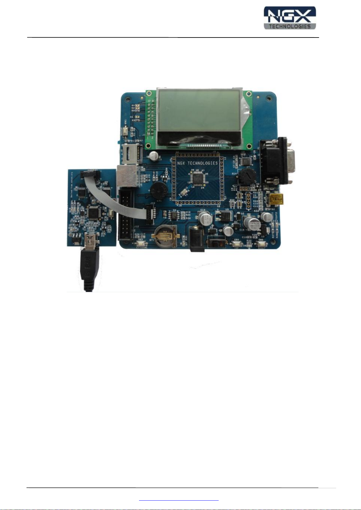
The BLUEBOARD-LPC11U24/37 board has on board Cortex SWD/JTAG 10-pin box, the one end of
the 10-pin cable is connected to NGX CoLinkEx and the other end is connected to BLUEBOARD-
LPC11U24/37 as shown in the below image.
Fig. 5
The hardware setup is now ready for programing a BLUEBOARD-LPC11U24/37 board with NGX
CoLinkEx and Coocox CoIDE.

Quick Start Guide: BlueBoard-LPC11U24/37
7www.ngxtechnologies.com
2.0 BLUEBOARD-LPC11U24/37 OVERVIEW
2.1 INTRODUCTION
The NGX BLUEBOARD-LPC11U24/37 is a compact and versatile evaluation platform for the NXP's
Cortex-M0-based MCU. NGX's evaluation platforms are generally not tied up to any particular
debugger or compiler/IDE. However it is not practical to test and ensure that the solution would work
out of box with all the available debuggers and compilers/IDE. As long as the compiler supports the
particular MCU and the debugger supports the standard debug interfaces like the SWD you can use this
platform with any tool. The board is supported by extensive sample examples allowing you to focus on
the application development.
2.2 Board Features
Following are the salient features of the board
Dimensions: 110mm X 110mm
Two layer PCB (FR-4 material)
Power: DC 6.5V with power LED On-board linear regulators generate +3.3V/500mA and
+5V/500mA from power supply USB connector (as alternate power source)
10 pin, 20 pin CORTEX debug connector for SWD (Serial Wire Debug)
ISP, Wakeup, External Interrupt and reset switch
12.0000 MHz crystal for MCU, 32Khz crystal for RTC
Extension headers for all MCU pins
RS232 connector, PS2 connector, Micro SD/MMC card connector, USB type-B mini connector
with link-LED
64x128 parallel graphical LCD with Backlight control
High accuracy external RTC connected on I2C bus
RTC battery holder
10K pot for ADC
Note: The BLUEBOARD-LPC11U24/37 has support for both 20 pin and 10 pin debug header. You don't
need to buy a 20pin to 10pin converter (board which costs 10-15 USD).

Quick Start Guide: BlueBoard-LPC11U24/37
8www.ngxtechnologies.com
2.3 Block Diagram
Fig. 6
2.4 MCU Features
ARM Cortex-M0 processor, running at frequencies of up to 50 MHz
ARM Cortex-M0 built-in Nested Vectored Interrupt Controller (NVIC)
Non-Maskable Interrupt (NMI) input selectable from several input sources
System tick timer
LPC11U24 offers 32 KB (LPC11U37 offers 128-KB) on-chip flash program memory
Up to 4 KB on-chip EEPROM data memory
LPC11U24 offers Up to 10 KB (LPC11U37 offers 12-KB) SRAM data memory
16 KB boot ROM
In-System Programming (ISP) and In-Application Programming (IAP)

Quick Start Guide: BlueBoard-LPC11U24/37
9www.ngxtechnologies.com
ROM-based USB drivers. Flash updates via USB supported
ROM-based 32-bit integer division routines
Standard JTAG (Joint Test Action Group) test interface
Serial Wire Debug
40 General-Purpose I/O (GPIO) pins
Up to 8 GPIO pins can be selected as edge and level sensitive interrupt sources
Two GPIO grouped interrupt modules
High-current source output driver (20 mA) on one pin
High-current sink driver (20 mA) on true open-drain pins
Four general-purpose counter/timers
Programmable Windowed WatchDog Timer (WWDT)
10-bit ADC with input multiplexing among eight pins
USB 2.0 full-speed device controller
USART (Universal Synchronous Asynchronous Receiver/Transmitter)
Two SSP (Synchronous Serial Port) controllers
I2C-bus interface supporting the full I2C-bus specification and Fast-mode Plus
Crystal Oscillator with an operating range of 1 MHz to 25 MHz
12 MHz high-frequency Internal RC oscillator (IRC)
Internal low-power, low-frequency WatchDog Oscillator (WDO)
PLL allows CPU operation up to the maximum CPU rate
A second, dedicated PLL is provided for USB
Clock output function with divider
Integrated PMU (Power Management Unit)
Power profiles residing in boot ROM
Four reduced power modes
Processor wake-up
Power-On Reset (POR)
Brownout detect with four separate thresholds for interrupt and forced reset
Unique device serial number for identification
Single 3.3 V power supply (1.8 V to 3.6 V)
Temperature range -40 °C to +85 °C
For the most updated information on the MCU please refer to NXP's website.

Quick Start Guide: BlueBoard-LPC11U24/37
10 www.ngxtechnologies.com
3.0 BLUEBOARD-LPC11U24/37 Hardware Description
3.1 Introduction
The NGX BLUEBOARD-LPC11U24/37 is based on ARM Cortex-M0 microcontroller from NXP.
LPC11U24 offers 32-KB Flash memory (LPC11U37 offers 128-KB Flash memory), 4-KB on-chip
EEPROM data memory, 50-MHz operation, I2C controller with data rate of up to 1 Mbit/s, USB 2.0
full-speed device controller, and wide range of peripherals. Refer to the LPC11U24 and LPC11U37 data
sheet for complete device details.
BLUEBOARD-LPC11U24/37 microcontroller is factory-programmed with a quick start demo program.
The quick start program resides in the BLUEBOARD-LPC11U24/37 on-chip Flash memory and runs
each time power is applied, unless the quick start has been replaced with a user program.
3.2 Board Image with pointer to each peripheral & connectors
Fig 7
Este manual sirve para los siguientes modelos
1
Tabla de contenidos
Manuales populares de Hardware de computadora de otras marcas

EMC2
EMC2 VNX Series Manual del propietario

Panasonic
Panasonic DV0PM20105 Manual de usuario

Mitsubishi Electric
Mitsubishi Electric Q81BD-J61BT11 Manual de usuario

Gigabyte
Gigabyte B660M DS3H AX DDR4 Manual de usuario

Raidon
Raidon iT2300 Manual de usuario

National Instruments
National Instruments PXI-8186 Manual de usuario