NetWave NWTAP-100 Manual de usuario

NWTAP-100 user guide
1
Netwave Proprietary and Confidential
NWTAP-100
Wireless Tap
User Guide
Preliminary Release 1.0, Issue 2
March 12, 2007
Netwave Co., Ltd.

NWTAP-100 user guide
2
Netwave Proprietary and Confidential
Contents
1. Overview ...................................................................................................................3
1.1. Introduction........................................................................................................3
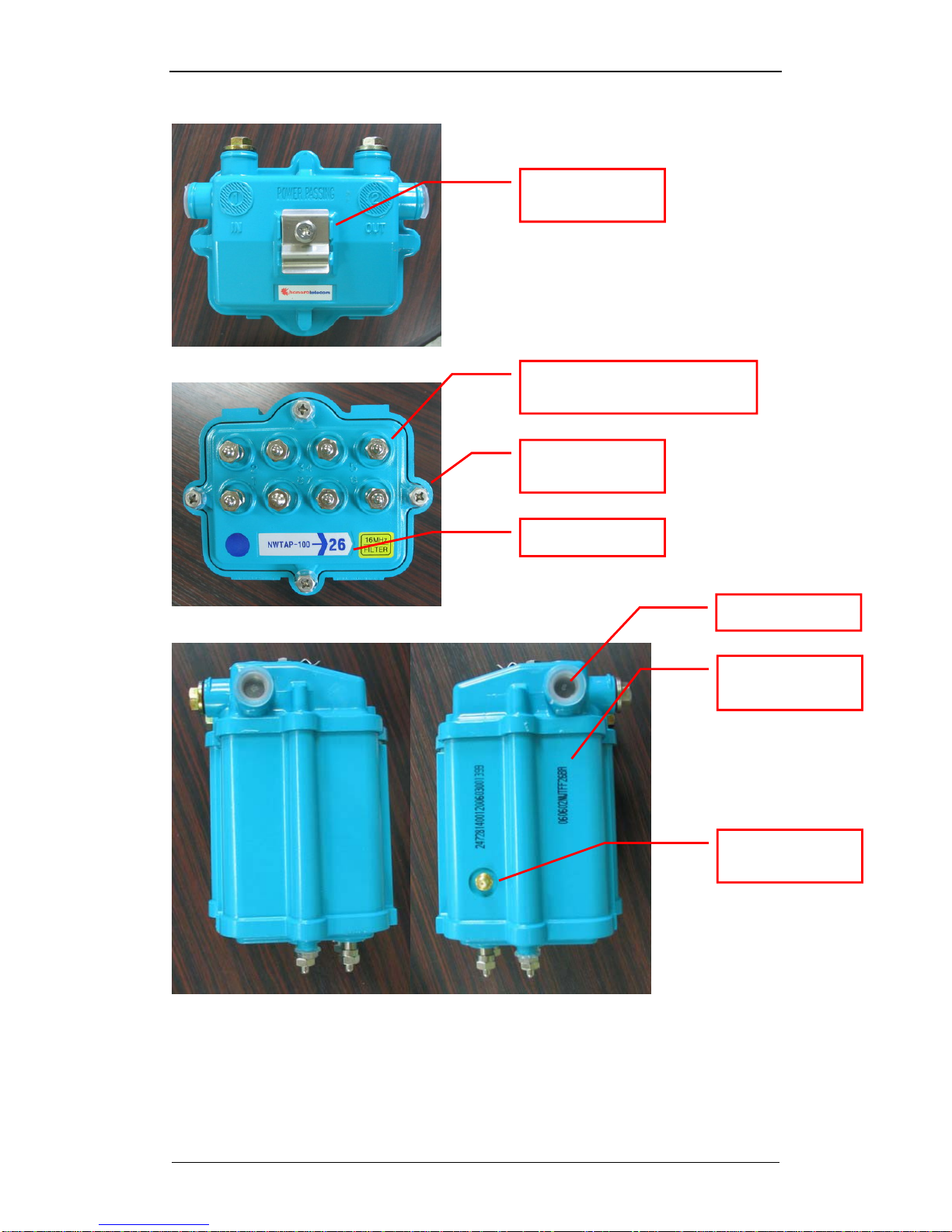
1.2. Product Description...........................................................................................4
2. Installation...............................................................................................................11
2.1. Unpacking and Content Checking...................................................................11
2.2. Remove Current Tap.......................................................................................12
2.3. Install the Wireless Tap...................................................................................12
2.4. Attach the Antenna..........................................................................................13
2.5. Insert the Power ..............................................................................................14
2.6. Check for Proper Operation ............................................................................14
2.7. Performance Measurement.............................................................................16
3. WLAN Site Survey and Planning.............................................................................17
3.1. Location...........................................................................................................17
3.2. Radio Link Path...............................................................................................17
3.3. RF Channel Selection .....................................................................................18
3.4. Performance check .........................................................................................18
4. Configuration...........................................................................................................19
4.1. Webui based configuration..............................................................................19
4.2. WIRELESS......................................................................................................22
4.3. Wireless/Basic submenu.................................................................................23
4.4. Wireless/Security submenu.............................................................................23
4.5. Wireless/Access Control submenu..................................................................24
4.6. Wireless/Advanced submenu..........................................................................25
4.7. TOOLS ............................................................................................................26
4.8. Gateway ..........................................................................................................27
4.9. Telnet based configuration..............................................................................28
4.10. SNMP based configuration..............................................................................31
4.11. Software upgrade............................................................................................31
5. Troubleshooting.......................................................................................................32
5.1. Troubleshooting for various symptoms............................................................32
5.2. Disassembling the wireless tap.......................................................................33
6. Appendix .................................................................................................................38
6.1. Ordering table..................................................................................................38
6.2. NWTAP-100 specifications..............................................................................38
6.3. FCC warning ...................................................................................................41

NWTAP-100 user guide
3
Netwave Proprietary and Confidential
1. Overview
1.1. Introduction
This document describes the features of the wireless tap NWTAP-100 as well as how
it can be installed to provide the most effective service to end users.
The NWTAP-100 is an outdoor hardened wireless lan access point solution which
uses an internal cable modem as the backbone interface and AC line power from the
feeder cable for power. The wireless LAN tap-off is an all-in-one unit which consists
of a cable modem, WiFi access point, power supply unit, antenna and tap-off in an
outdoor-hardened housing.
It provides a low cost and easy to install WiFi access hotspot to homes and
businesses by simply removing the old tap and installing the wireless tap.
Standards based
The internal cable modem is DOCSIS 2.0 compliant based on the Broadcom
BCM3349. It is fully interoperable with all CMTS models available in the market
today.
The internal WiFi is based on the 802.11g standard which is backwards compatible
to the 802.11b. The wireless chipset is based on the Broadcom BCM4318.
Security
Security is of utmost importance in todays wireless networks which are exposed to
hackers and other mallicit users. The NWTAP-100 fully supports all the latest 802.11
security enhancements including WPA2.
Future proofed
The NWTAP-100 supports remote software upgrade via TFTP. The modem will
maintain the current version of software while downloading the new version in order
to provide crash proofing. Netwave will continue to include enhancements and
customizations to the existing software so that customers can continue to use the
wireless tap most effectively for many years.
Flexible service platform
The software running the wireless tap is a full featured gateway which can be used to
support commercial high speed access to homes and offices or provide public
hotspot service.
The flexible antenna mounts can be used to support a tap housing mounted antenna.
Since the antenna output is based on an SMA connector, various off-the-shelf
antennas may also be used.
The unit can be strand mounted or can be mounted at the side of buildings and
provides WiFi access as well as wired CATV signals.

NWTAP-100 user guide
4
Netwave Proprietary and Confidential
1.2. Product Description
1.2.1. NWTAP-100
The following is a list of NWTAP-100’s main features.
Includes an internal DOCSIS 2.0 cable modem
Trunk AC power can be used to power the wireless tap
Trunk input and output as well as subscriber output ports are in the same
configuration as a conventional tap-off
Conventional tap-off can be removed and replaced with the wireless tap
without impacting the electrical characteristics of the CATV signal
coming off of the 5C connectors
802.11b/g compliant wireless lan service is provided
Antenna connection is made via an SMA female connector located at the
side of the wireless tap
8-tap front
8-tap back
Antenna fixing
screw holes
Antenna SMA
connector
Subscriber F-connector
with terminating load
5/8” input/output
connector
Center pin seizing
screw cover

NWTAP-100 user guide
5
Netwave Proprietary and Confidential
8-tap top
8-tap bottom
8-tap sides
Strand mounting
fixture
Subscriber F-connector with
terminating load
Faceplate
screws
Product serial
marking.
Antenna SMA
connector
Tap dB value
Plastic cap
060602 : production year+month+date
NWT : product name
FF26BA : MAC address which follows
the OUI “000200”

NWTAP-100 user guide
6
Netwave Proprietary and Confidential
16-tap front
16-tap back
16-tap bottom
16-port faceplate
adaptor

NWTAP-100 user guide
7
Netwave Proprietary and Confidential
16-tap sides
Fig. 1 NWTAP-100 external features

NWTAP-100 user guide
8
Netwave Proprietary and Confidential
Fig. 2 NWTAP-100 block diagram
As shown in fig. 2, the trunk line RF is sampled to the tap-off splitter circuit as in a
conventional tap-off but part of this signal is also coupled to an internal cable modem.
The cable modem then transfers the Ethernet packets to the wireless part for
communication via 802.11b/g radio.
The AC power existing in the trunk network is also sampled by the power part so that
the DC powering for the cable modem and the wireless lan can be provided.

NWTAP-100 user guide
9
Netwave Proprietary and Confidential
cable
modem
-Y dB
-0.5dB
(connector)
-0.5dB
(connector)
-17dB
-12dB
Main spliiter
-1dB
trunk IN trunk OUT
subscriber OUT
-1dB
(16Mhz HPF)
Fig. 3 RF signal level within the wireless tap
The above figure shows the RF signal level attenuation as they pass through the
wireless tap with 8 subscriber ports.
The RF signal level output at the subscriber ports are attenuated by approximately,
-Y-1-0.5-1-0.5-12 dB
The actual tap value in dB displayed at the bottom of the tap excludes the 1dB
attenuation for the 16Mhz HPF and -1dB attenuation for the cable modem.
-Y-0.5-0.5-12 dB
The RF signal level output at the cable modem is attenuated by approximately,
-Y-1-0.5-17 dB
This level should be considered so that the appropriate RF level is input into the
cable modem. The cable modem input level should be within the range -
15~+15dBmV.
The main splitter is implemented in the form of a plug-in type coupler which allows
this value to be easily changed in the field as shown in section 5.2.2.

NWTAP-100 user guide
10
Netwave Proprietary and Confidential
1.2.2. Antenna
The antenna connection via a standard SMA connector and a flexible antenna
attaching structure on the housing consisting of 12 screw positions allow a wide
range of antennas to be supported. If the antenna size is too big for direct attachment
to the housing, it maybe attached to a separate stable structure and connected via
RF cable from the SMA connector.
“This device uses an SMA type connector only”
RF exposure compliance information.
“The antenna used for this transmitter must be installed to provide a separation
distance of at least 20cm from all persons and must not be co-located or operating in
conjunction with any other antenna or transmitter.”
Tabla de contenidos
Otros manuales de Punto de acceso inalámbrico de NetWave


