netsys NT205B Manual de usuario

NT205B
5
5
5.
.
.7
7
7M
M
Mb
b
bp
p
ps
s
s
G
G
G.
.
.s
s
sh
h
hd
d
ds
s
sl
l
l
b
b
bi
i
is
s
s
L
L
LA
A
AN
N
N
E
E
Ex
x
xt
t
te
e
en
n
nd
d
de
e
er
r
r
w
w
wi
i
it
t
th
h
h
4
4
4
E
E
Et
t
th
h
he
e
er
r
rn
n
ne
e
et
t
t
U
U
Us
s
se
e
er
r
r’
’
’s
s
s
M
M
Ma
a
an
n
nu
u
ua
a
al
l
l

NT205B User’s Manual
VER_A1
2
Copyright
Copyright © 2011 by National Enhance Technology Corp. All rights reserved.
Trademarks
NETSYS is a trademark of National Enhance Technology Corp.
Other brand and product names are registered trademarks or trademarks of their respective holders.
Legal Disclaimer
The information given in this document shall in no event be regarded as a guarantee of conditions or characteristics. With respect
to any examples or hints given herein, any typical values stated herein and/or any information regarding the application of the
device, National Enhance Technology Corp. hereby disclaims any and all warranties and liabilities of any kind, including without
limitation warranties of non-infringement of intellectual property rights of any third party.
Statement of Conditions
In the interest of improving internal design, operational function, and/or reliability, NETSYS reserves the right to make changes to
the products described in this document without notice. NETSYS does not assume any liability that may occur due to the use or
application of the product(s) or circuit layout(s) described herein.
Maximum signal rate derived form IEEE Standard specifications. Actual data throughput will vary. Network conditions and
environmental factors, including volume of network traffic, building materials and construction, and network overhead lower actual
data throughput rate.

NT205B User’s Manual
VER_A1
3
Safety Warnings
For your safety, be sure to read and follow all warning notices and instructions before device use.
DO NOT open the device or unit. Opening or removing covers can expose you to dangerous high voltage points or other
risks. ONLY qualified service personnel can service the device. Please contact your vendor for further information.
Use ONLY the dedicated power supply for your device. Connect the power cord or power adaptor to the right supply voltage
(110V AC in North America or 230V AC in Europe).
DO NOT use the device if the power supply is damaged as it might cause electrocution. If the power supply is damaged,
remove it from the power outlet. DO NOT attempt to repair the power supply. Contact your local vendor to order a new power
supply.
Place connecting cables carefully so that no one will step on them or stumble over them. DO NOT allow anything to rest on
the power cord and do NOT locate the product where anyone can work on the power cord.
DO NOT install nor use your device during a thunderstorm. There may be a remote risk of electric shock from lightning.
DO NOT expose your device to dampness, dust or corrosive liquids.
DO NOT use this product near water, for example, in a wet basement or near a swimming pool.
Connect ONLY suitable accessories to the device.
Make sure to connect the cables to the correct ports.
DO NOT obstruct the device ventilation slots, as insufficient airflow may harm your device.
DO NOT store things on the device.
DO NOT use the device outside, and make sure all the connections are indoors. There may be a remote risk of electric
shock from lightning.
Be careful when unplugging the power, because the transformer may be very hot.
Keep the device and all its parts and accessories out of children’s reach.
Clean the device using a soft and dry cloth rather than liquid or atomizers. Power off the equipment before cleansing it.
This product is recyclable. Dispose of it properly.

NT205B User’s Manual
VER_A1
4
Table of Contents
COPYRIGHT........................................................................................................................................................................................................ 2
SAFETY WARNINGS.......................................................................................................................................................................................... 3
CHAPTER 1. DESCRIPTION............................................................................................................................................................................ 6
1.1
P
RODUCT
D
ESCRIPTION
.................................................................................................................................................................................. 6
1.2
S
PECIFICATION
............................................................................................................................................................................................... 7
1.3
A
PPLICATION
.................................................................................................................................................................................................. 8
1.4
SHDSL
SYSTEM COMPONENTS
....................................................................................................................................................................... 8
1.5
F
RONT
P
ANEL
LED
S
I
NDICATORS
................................................................................................................................................................... 8
1.6
R
EAR
P
ANEL
C
ONNECTORS
.......................................................................................................................................................................... 10
CHAPTER 2. PACKAGING ............................................................................................................................................................................. 12
2.1
C
HECKING
P
ACKAGE
C
ONTENTS
.................................................................................................................................................................. 12
2.2
P
REPARE FOR
I
NSTALLATION
........................................................................................................................................................................ 12
CHAPTER 3. LOG ON...................................................................................................................................................................................... 13
3.1
M
ENU
T
REE
.................................................................................................................................................................................................. 15
3.2
M
AIN
M
ENU
................................................................................................................................................................................................. 17
3.3
C
ONSOLE
S
CREEN
C
ONVENTION
.................................................................................................................................................................. 17
CHAPTER 4. CONFIGURATION ................................................................................................................................................................... 19
4.1
C
ONFIGURE
D
EVICE
T
YPE
............................................................................................................................................................................ 21
4.2
C
ONFIGURE
A
NNEX
M
ODE
........................................................................................................................................................................... 21

NT205B User’s Manual
VER_A1
5
4.3
C
ONFIGURE
DSL
R
ATE
................................................................................................................................................................................ 21
4.4
C
ONFIGURE
LAN
I
NTERFACE
....................................................................................................................................................................... 21
4.5
VLAN
SETTING
............................................................................................................................................................................................ 23
4.6
F
ACTORY
D
EFAULT SETTING
........................................................................................................................................................................ 25
4.7
S
AVE CONFIGURATION
................................................................................................................................................................................. 25
CHAPTER 5. PERFORMANCE MONITORING.......................................................................................................................................... 26
CHAPTER 6. INVENTORY.............................................................................................................................................................................. 28
APPENDIX A: COMPLIANCE AND SAFETY INFORMATION................................................................................................................ 29
NT205B User’s Manual
VER_A1
6
Chapter 1.
Description
1.1 Product Description
The NT205B, a SHDSL (Single-pair High-bit-rate Digital Subscriber Line) LAN Extender, provides a broadband transmission with
bandwidth up to 5.696Mbps over a single pair of copper wires for LAN connection between two local area networks. NT205B
provides a console port for users to configure the settings and to monitor the DSL connection status.
NT205B conforms to ITU-T G.991.2, the GSHDSL requirements. Each NT205B can be configured as either STU-C for the central
side or STU-R for the remote side. A pair of NT205B offers a cost effective symmetrical broadband solution for bandwidth-hungry
applications such as LAN-to-LAN connection, Internet, etc.
Features:
ITU G.991.2 Annex A, Annex B and Annex F
Symmetrical downstream and upstream data rates from 192Kbps to 5.696Mbps
Auto-Negotiation for 10/100 BaseT
Auto-MDIX for Auto Ethernet Tx/Rx Swap

NT205B User’s Manual
VER_A1
7
1.2 Specification
G.SHDSL line
Line Coding: 16 TC-PAM or 32 TC-PAM
Line Rate: 192K bps ~ 5696 Kbps
Standard: ITU-T G.991.2, Annex A, Annex B and Annex F selectable
LAN interface
Mac Address filtering bridge up to 2K Mac address learning
Bridge: IEEE 802.1D transport, self-learning
VLAN Tag based & Port Based
Bandwidth Control for Ethernet Port
Physical interfaces
4 x RJ45 10/100Mbs Ethernet ports
1 x RJ-11 port for G.SHDSL connection
One console port: DB-9 Female
DC 5 V power input

NT205B User’s Manual
VER_A1
8
1.3 Application
Following Figure shows a point to point application for user interface LAN
Ethernet Bridging
1.4 SHDSL system components
NT205B modem (CO) or NT205B modem (RT) in a working pair.
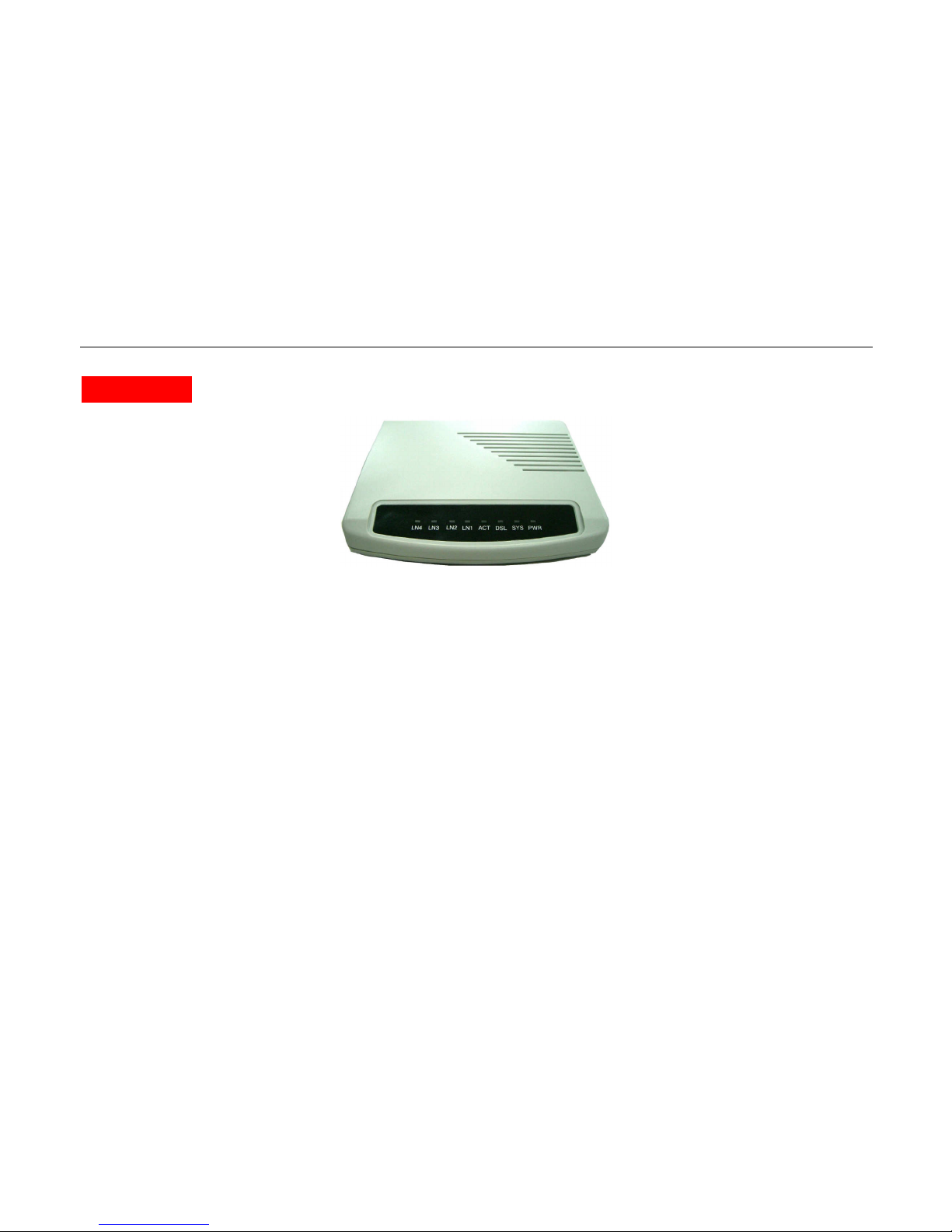
1.5 Front Panel LEDs Indicators
There are eight LED indicators on the front panel of NT205B. They show the statuses of the device.
LANLAN

NT205B User’s Manual
VER_A1
9
The functions of LED indicators are described in the following table:
LED
Color Status Meaning
PWR
Orange
Steady
Off The device is on.
The device is off.
CO Orange
Steady The device is configured to CO mode
RT Orange
Steady The device is configured to RT mode
DSL
Orange
Steady
Blinking
Off
The device is Sync Status.
The link is synchronizing - this may take several
minutes.
The device is unplugged or disconnected.
LN1 Orange
Steady Link 1 - The LAN connection is successfully
established.
LN2 Orange
Steady Link 2 - The LAN connection is successfully
established.
LN3 Orange
Steady Link 3 - The LAN connection is successfully
established.
LN4 Orange Steady Link 4 - The LAN connection is successfully established.

NT205B User’s Manual
VER_A1
10
1.6 Rear Panel Connectors
The rear panel connectors connecting the device to the LAN and xDSL network are illustrated as below.
LAN Interface characteristic
LAN Interface ( RJ-45 port ) located in NT205B’s rear panel meets to IEEE 802.3 or IEEE 802.3u request and supports 10/100
Base-T auto test and half/all touble works model operation, bridge can provide up to 128 MAC address and MAC address filtration
function, meets IEEE 802.1d protocol requirement.
RJ-45 wire
Figures separable shows as following :
Power Adapter
RJ-11
Phone Line
(xDSL)
RS-232
Emulator Terminal
VT-100
LAN
RJ-45
PC
Console
Rear Panel and Installation
PC
Tabla de contenidos
Otros manuales de Extensor de netsys

netsys
netsys NV-320DP Manual de usuario

netsys
netsys NV-320SE Manual de usuario

netsys
netsys NV-202P Manual de usuario

netsys
netsys NV-202M Manual de usuario

netsys
netsys NB-301A Manual de usuario

netsys
netsys NV-520G Manual de usuario

netsys
netsys NV-202G Manual de usuario

netsys
netsys NVF-200SE/PD KIT Manual de usuario


