Net Optics Director Manual de usuario

User Guide
Data Monitoring Switch
Doc. PUBDIRU Rev. 3, 11/08
www.netoptics.com
1
2
B
A
AB
IDS
Analyzer 2
Analyzer 1
RMON 1 RMON 2
Forensic

PLEASE READ THESE LEGAL NOTICES CAREFULLY.
By using a Net Optics Director device you agree to the terms and conditions of usage set forth by Net Optics, Inc.
No licenses, express or implied, are granted with respect to any of the technology described in this manual. Net Optics retains all intellectual
property rights associated with the technology described in this manual. This manual is intended to assist with installing Net Optics products into
your network.
Trademarks and Copyrights
© 2008 by Net Optics, Inc. Net Optics is a registered trademark of Net Optics, Inc. Director is a trademark of Net Optics, Inc. Additional company
and product names may be trademarks or registered trademarks of the individual companies and are respectfully acknowledged.
Additional Information
Net Optics, Inc. reserves the right to make changes in specications and other information contained in this document without prior notice. Every
effort has been made to ensure that the information in this document is accurate.

Director
Contents
Chapter 1
Introduction
Key Features ............................................................................2
About this Guide.........................................................................3
DirectorArchitecture ..................................................................... 4
USB port ...............................................................................5
Director Management .....................................................................5
Typical Application.......................................................................6
In-line Monitoring of 10 Gigabit Links .......................................................8
DirectorFrontPanel......................................................................9
Director Rear Panel...................................................................... 10
Chapter 2
Installing Director
Plan the Installation......................................................................12
Unpack and Inspect the Director device ......................................................12
InstallDirectorNetworkModules ..........................................................13
Install SFP and XFP Monitor port Modules ...................................................13
Rack Mount the Director device ............................................................ 13
ConnectPowertoDirector................................................................14
ConnectthelocalCLIInterface............................................................14
Connect the remote CLI Interface........................................................... 15
LogintotheCLI........................................................................16
Congure Director using the CLI ........................................................... 17
UsingtheCLICommandHistoryBuffer.....................................................21
Connect Span Ports to Director.............................................................22
Connect Director With In-line Network Links .................................................23
ConnectMonitoringToolstoDirector....................................................... 24
Congure a Matrix Switch connection in Director.............................................. 24
Check the Installation ....................................................................24

Director
Chapter 3
Conguring Filters Using the CLI
Syntax ................................................................................25
Copy Trafc From Any Network Port to Any Monitor Port....................................... 26
Aggregate Trafc From Any Set of Network Ports to Any Monitor Port............................. 26
Regenerate Trafc to Any Set of Monitor Ports ................................................27
Create Filters...........................................................................28
Create Complex Filters ................................................................... 29
View lters ............................................................................30
Work with congurable 10 Gigabit ports ..................................................... 31
Understand lter interactions ..............................................................33
Understand pending and active lters........................................................ 36
Chapter 4
Daisy-chaining Multiple Director Chassis .............................................. 40
Appendix A
Director Specications........................................................................... 41
Appendix B
Command Line Interface ........................................................................ 43
Filter parameters ........................................................................49
Appendix C
Protocol Numbers ................................................................................... 51
Limitations on Warranty and Liability .................................................... 54

Director
1
Chapter 1
Introduction
Net Optics Director is a key component for building a comprehensive, consolidated monitoring infrastructure for both
network management and security. It extends the range of visibility for data monitoring across converged data and
digital voice networks, while eliminating monitoring port contention and minimizing the number of tools needed to
optimally manage the network.
A single Director device enables you to tap into multiple network links, and direct their trafc to multiple monitoring
ports. It includes aggregation and regeneration functions, so the link-to-monitor-port mapping can be one-to-one,
one-to-many, many-to-one, or many-to-many. In addition, it provides ltering: Each Monitor port can be programmed
to receive only trafc meeting user-dened lter criteria based on protocol, source and destination addresses, and
other criteria. This ltering capability enables specic types of trafc such as voice over IP (VoIP) to be directed to
particular monitoring tools.
Matrix switching, aggregation, and regeneration
Each Director chassis supports up to 12 in-line network links or 28 Span ports. For monitoring, up to 14 ports are
provided. Network and Span ports can be aggregated and regenerated to output ports in almost any combination.
Modular design
Director is modular to provide conguration exibility.
Director Network Modules (DNMs) support SX (multi-mode) and LX (single-mode) ber links and 10/100/1000 •
Copper links.
Each DNM provides either 6 in-line network links or 12 Span ports.•
The Director Chassis includes two DNM slots; they can be populated with the same or different DNM types.•
Ten 1-Gigabit Monitor ports are SFP-based, accepting any mix of Copper, SX, and LX interface modules.•
Four 10-Gigabit ports are XFP-based, accepting SR, LR, and ER interface modules. •
Flexible 10 Gigabit support
Four 10 Gigabit ports can be congured as Network, Span, or Monitor ports. They can be congured for the same or
different functions. Trafc from multiple 1-Gigabit Network or Span ports can be aggregated to a 10-Gigabit Monitor
port. Conversely, trafc from a 10 Gigabit Network or Span port can be dis-aggregated to multiple 1 Gigabit Monitor
ports through appropriate ltering. For example, trafc from different IP address ranges could be directed to separate
Monitor ports.
Expandable
Two 10 Gigabit ports on the rear of the unit enable daisy-chaining up to ten Director chassis to expand the number of
available ports, for a total of 380 ports in a fully expanded system (when available).
Monitor port-based ltering
Director avoids the confusion of pre-ltering versus post-ltering by strictly tying ltering to the Monitor ports. Each
Monitor port can be congured to have trafc from any number of Network or Span ports directed to it, and each Monitor
port applies up to 30 protocol-, address-, and utilization-based lters to the trafc.

Director
2
Key Features
Ease of Use
Tap, aggregation, regeneration, matrix switch, and lter functions in a single device•
19-inch rack frame, 1U high•
Front-mounted connectors for quick and easy installation•
LED indicators show Power, Link, and Activity status•
Modular design for conguration exibility•
RMON statistics, including network utilization ltering; data can be used to assemble XML-based end-user reports, •
or it may be exported to a third party reporting tool such as a protocol analyzer
Text-based command-line interface (CLI) available through RS-232 serial port•
CLI also available remotely over secure SSH connection•
Field-upgradeable software•
Compatible with all major manufacturers’ monitoring devices, including protocol analyzers, probes, and intrusion•
detection and prevention systems
Monitor port Filtering
1,000 lter elements per a chassis•
Exclusive (drop matched packets) and inclusive (pass matched packets) lters•
Filters based on IP protocol, IP addresses, layer 4 ports, MAC addresses, and VLANs•
Source and destination MAC addresses, or ranges of addresses•
Source and destination IP addresses, or ranges of addresses•
Source and destination ports, or ranges of ports•
Supports IPv4 and IPv6 protocols•
VLAN•
Protocols: all IP protocols such as ICMP, TCP, UDP, and RDP•
Passive, Secure Technology
Passive access at up to 10 Gbps•
In-line links do not interfere with the data stream or introduce a point of failure•
Optimized and tested for 10, 100, and 1000Mbps copper and 1 and 10 Gpbs ber networks•
Redundant power to maximize uptime•
In-line links default to open under a complete power-fail condition, ensuring network availability•
FCC, CE, VCCI, C-Tick, and WEEE certied•
Fully RoHS compliant•
Unsurpassed Support
Net Optics offers technical support throughout the lifetime of your purchase. Our technical support team is•
available from 8:00 to 17:00 Pacic Time, Monday through Friday at +1 (408) 737-7777 and via e-mail at

Director
3
About this Guide
Please read this entire guide before installing Director. This guide applies to the following part numbers:
Chassis Part Number Description
DIR-3400 Director Main Chassis with 10 SFP monitor ports
DIR-7400 Director Main Chassis with 10 SFP monitor ports, 2 XFP 10GbE ports, 2 XFP uplink ports
DNM Part Number Description
DNM-100 6-Port 10/100/1000 Copper In-Line Module
DNM-110 12-Port 10/100/1000 Copper Span Module
DNM-200 6-Port Gigabit SX Fiber 62.5μm In-Line Module
DNM-210 12-Port Gigabit SX Fiber 62.5μm Span Module
DNM-220 6-Port Gigabit SX Fiber 50μm In-Line Module
DNM-230 12-Port Gigabit SX Fiber 50μm Span Module
DNM-300 6-Port Gigabit LX Fiber In-Line Module
DNM-310 12-Port Gigabit LX Fiber Span Module
DNM-320 6-Port Gigabit ZX Fiber In-Line Module
DNM-330 12-Port Gigabit ZX Fiber Span Module

Director
4
Director Architecture
The following diagram shows a schematic view of the architecture of the Director device shown as a Matrix Switch with
ltering. The black dots indicate aggregating Matrix Switch connections between Network Ports and Monitor Ports.
K e y :
Network or Span port
Monitor Port
Aggregating switch conection
Dim Alternate configurations for 10 GbE XFP ports
DNM with
6 in-line
network ports
DNM with
12 Span or
out-of-band
network ports
Four configurable
10GbE XFP ports
10 SFP monitor ports
Filters
n2.5
n2.4
n2.3
n2.2
n2.1
n2.10
n2.9
n2.12
n2.11
n2.8
n2.7
n2.6
n1.1
n1.3
n1.5
n1.7
n1.9
n1.11
n1.2
n1.4
n1.6
n1.7
n1.10
n1.12
t1.1
t1.1
t2.2t2.1t1.2
t1.2
t2.1
t2.2
m.1 m.2 m.3 m.4 m.5 m.6 m.7 m.8 m.9 m.10
Director internal architectureFigure 1:
Director can be viewed as a matrix switch with up to 28 inputs, or Network ports, and 14 outputs, or Monitor ports.
Any number of inputs can be directed to each of the outputs; Director aggregates the trafc from those Network ports
and sends them to the Monitor ports. For example, the diagram shows:
Trafc from the rst in-line Network link (n1.1-n1.2) is being directed to the rst SFP Monitor port (m.1)•
Trafc from two in-line Network links (n1.3-n1.4 and n1.7-n1.8) plus three Span Network ports (n2.3, n2.7, •
and n2.11) is being aggregated and directed to the second SFP Monitor port (m.2)
Trafc from one in-line Network link (n1.11-n1.12) is being regenerated to two SFP Monitor ports (m.9 and m.10)•
The trafc from the in-line Network links to the Monitor ports may include the trafc being received at the odd-
numbered Network port (at the left side of the diagram), at the even-numbered Network port (at the right side of the
diagram), or both; the diagram doesn't include this level of detail.
In addition, lters (shown at the bottom of the diagram) are congured independently for each Monitor port, one or
more lters per port, and applied on the aggregated trafc for that port. For example, the second SFP Monitor port
could have two lters, where one lter selects the TCP trafc from the two in-line Network links and the second lter
selects the UDP trafc from the three Span Network ports.

Director
5
The inputs are divided into three groups: two DNMs plus the 10GbE ports. In-line DNM models support 6 in-line links,
while Span DNM models support 12 Span ports. The diagram shows one in-line and one Span DNM. Both in-line and
Span DNMs are available with either Copper or SX, LX, or ZX Fiber interfaces. Different DNM types can be mixed in
the same chassis, for example, one in-line Copper DNM and one Span Fiber DNM. The modules are hot-pluggable
for easy serviceability. One or both DNM slots can be populated. The DNM slots are numbered 1 for the slot on the left
and 2 for the slot on the right. If only one slot is populated, it should be slot 1.
The four congurable 10-Gigabit XFP ports are shown in the rst four columns and last four rows of the diagram. The
four dark black rows indicate that all four ports are congured as Span inputs. The four dimmed columns indicate that
the ports can alternately be congured as Monitor ports. The four ports may be congured as:
Both Span•
Both Monitor•
One Span and one Monitor•
In addition, the two 10 Gigabit ports on the back of the chassis (t2.1, t2.2) can be used as uplink ports to daisy-chain
chassis for expansion.
USB port
A USB port located on the back is reserved for future functionality.
Director Management
Director can be congured and managed using a command-line interface (CLI) that will be familiar to most network
administrators. The CLI runs locally over an RS-232 serial port or remotely over a secure SSH connection.
Net Optics GUI-based Indigo management tools, which will be available soon, include:
Web Manager• —A Web-browser based tool to manage a single Director (at a time) from anywhere in the world
System Manager• —An SNMP platform-based tool to mange all the Director and other Net Optics iTap-enabled
devices on your network
Director
6
Typical Application
The following diagram shows a typical application using Director to implement a comprehensive, consolidated monitoring
infrastructure.
www.netoptics.com
1
2
B
A
AB
IDS
Analyzer 2
Analyzer 1
RMON 1 RMON 2
Forensic
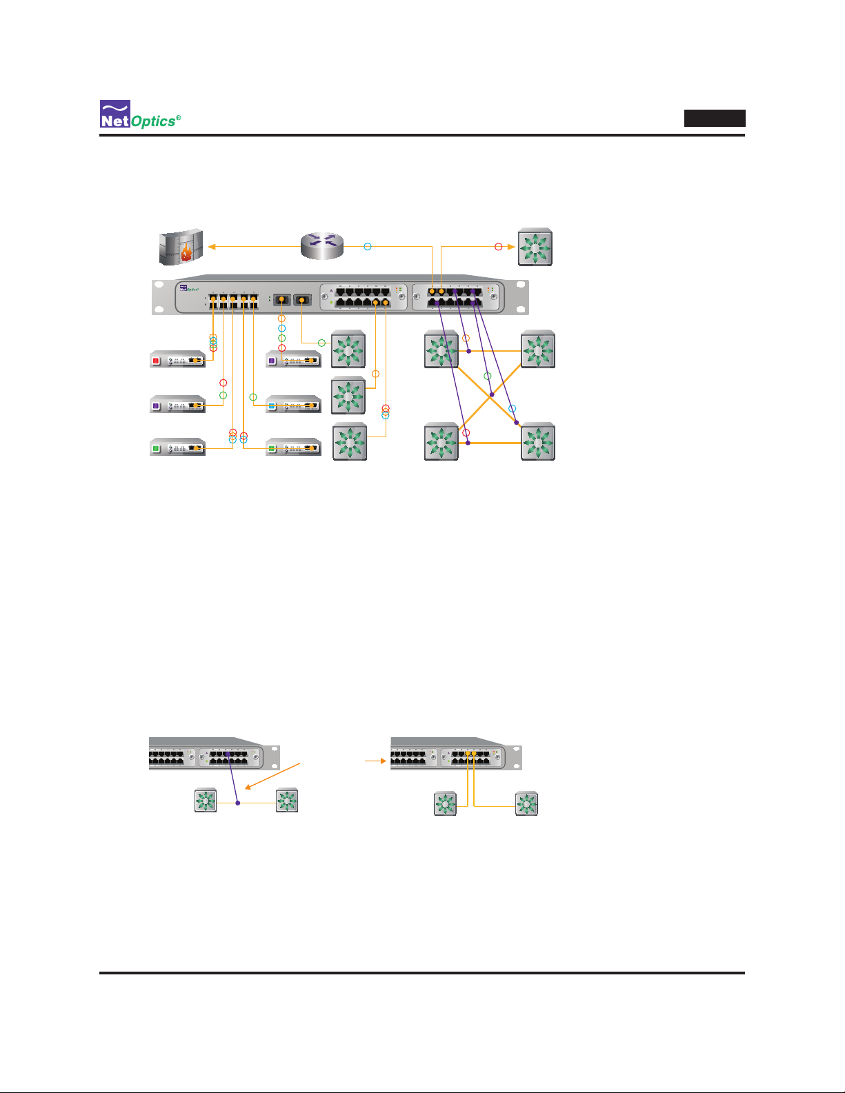
Director-centric network monitoring infrastructureFigure 2:
In this example, eight network links are monitored by six monitoring devices. The company's external access is protect-
ed by a rewall, shown in the upper left of the diagram. The link runs through a router, then in-line through Director,
and then to a switch that distributes trafc throughout a department.
Network Links
The rest of the department's switches are shown, but only the connections to Director are illustrated. The four depart-
ment switches shown in the lower right are cross-connected for fault tolerance. All four of the cross-connected links
are passed in-line through Director (as indicated by the slanting purple lines) so they can be thoroughly monitored for
performance tuning, security, and trouble-shooting. Because so many critical links pass in-line through Director, it's
good to know that they are completely passive connections—Director does not slow down or interfere with the in-line
trafc, and the links stay open to pass trafc even if both of the Director power supplies are removed. (When power
is removed, 10/100/1000 Copper in-line links may be dropped for a short period of time —less than 1 second—while
relays switch to open the link. Subsequently, the network re-establishes the links and trafc resumes owing.)
Purple line
indicates an
in-line Tap
Detail of in-line Taps shown in Figure 2Figure 3:
In the middle of Figure 2, three other departmental switches are monitored through their Span ports. One of the
switches handles 10GbE trafc, so its Span port goes to one of the Director 10GbE XFP ports. One of the other
switches' 1GbE Span ports carries three distinct types of trafc–e-mail, VoIP, and Web pages–as indicated by the three
colored circles on the Span link.
Otros manuales para Director
2
Tabla de contenidos
Otros manuales de Cambiar de Net Optics

Net Optics
Net Optics Director xStream Pro Manual de usuario

Net Optics
Net Optics 10/100/1000 Manual de usuario

Net Optics
Net Optics iBypass Manual de usuario

Net Optics
Net Optics 10/100/1000 Manual de usuario

Net Optics
Net Optics PA-CU-AR Manual de usuario

Net Optics
Net Optics Director Manual de usuario

Net Optics
Net Optics N-IDP-POBPSX-001, N-IDP-POBPLX Manual de usuario

Net Optics
Net Optics 4xN 10 Manual de usuario

Net Optics
Net Optics Director Manual de usuario

Net Optics
Net Optics BPO-HBSX-LC Manual de usuario


