Nemtek Taut Wire Node Guía del usuario

Taut Wire
Node
Installer Manual

1 Introduction 3
2 Disclaimer 3
3 NEMTEK Group Outlets 4
4 Hardware Setup 5
4.1 Technical Specifications - Node Board 5
4.2 Technical Specifications - Recommended Power Supply with Battery 5
4.3 Power Supply Installation 6
4.4 Node Board Layout 7
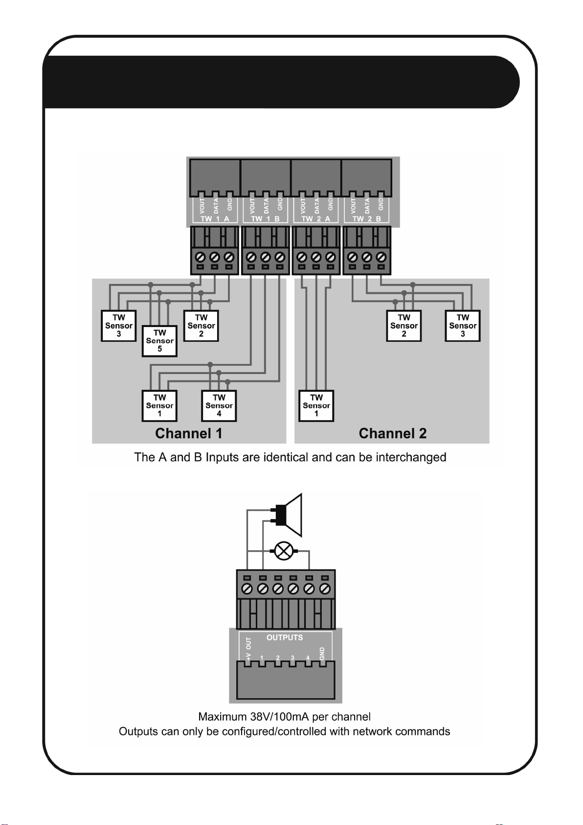
4.5 Connection Examples 8
4.5.1 Taut Wire Sensors 8
4.5.2 Digital Outputs 8
4.5.3 Digital Inputs 9
4.5.4 Relay Outputs 10
4.6 Jumper Configuration 11
5 Software Setup 12
5.1 Startup 12
5.2 User Menus 12
5.2.1 Default Menu 12
5.2.2 Tautwire Channel 1 State 12
5.2.3 Tautwire Channel 2 State 12
5.2.4 History Channel 1 12
5.2.5 History Channel 2 12
5.2.6 Event Log 13
5.2.7 System Restart 13
5.3 Installer Menus 13
5.3.1 Channel 1 Installer Menu 13
5.3.2 Channel 2 Installer Menu 16
5.3.3 Log Repeat Interval 16
5.3.4 Set TW Node Address 16
5.3.5 Save Configuration 16
5.3.6 System Restart 16
Appendix A: Error/Alarm Codes 17
Installer Notes 18
Table of Contents
2

1 INTRODUCTION
The NEMTEK Taut Wire Node provides a communication interface to the NEMTEK Taut Wire
sensors and other third-party security systems.
Two separate sensor input channels, each capable of accommodating 31 Taut Wire sensors are
provided. Each channel provides a relay output, which will energise a configurable wet or dry
contact in an alarm situation. The board can be easily set up by means of the on-board display,
pushbuttons and jumpers.
The Node 1 board offers a basic relay interface, whereas the Node 2 board is equipped with an
Ethernet port for network connectivity.
It is recommended that the Node board is installed inside the NEMTEK Power Supply Module,
which can be powered from a standard 230V/50Hz household socket and includes battery
backup in the event of power failure.
2 DISCLAIMER
NEMTEK Holdings (Pty) Ltd or any of its subsidiary companies does not guarantee that the
operation of the product will be uninterrupted or totally error free.
Product specifications may be altered without prior notification.
Introduction & Disclaimer
3

HEAD OFFICE
Tel: +27 (0)11 462 8283 Northriding Commercial Park
Fax: +27 (0)11 462 7132 Stand 251, Aintree Street, Northriding
Randburg, South Africa
EXPORTS
Fax: +27 (0)11 462 7132
EDENVALE
Tel: +27 (0)11 453 1970 Unit 4, Meadowdale Park
Fax: +27 (0)11 453 1858 Cnr. Dick Kemp & Herman Roads
Meadowdale, Edenvale, South Africa
CAPE TOWN
Tel: +27 (0)21 386-3742 27B Concord Crescent, Airport City
Fax: +27 (0)21 386-5573 Cape Town, South Africa
NELSPRUIT
Tel: +27 (0)13 752-2187 Waterval Ave, Riverside Industrial
Fax: +27 (0)13 752-2188 Nelspruit, South Africa
KWAZULU-NATAL
Tel: +27 (0)31 701-2125 19 Henwood Road
Fax: +27 (0)31 701-2125 Pinetown, South Africa
AUSTRALIA
Tel: (08) 9303 9855 Unit 5, 19 Innovation Circuit,
Email: nemtek@bigpond.net.au Wangara, 6065, Perth, WA, Australia
Website: www.nemtek.com
E-mail: nemtek@nemtek.com
Manufactured in South Africa
3 NEMTEK Group Outlets
4

4 Hardware Setup
5
4.1 Technical Specifications - Node Board
Parameter Value
Board Power Supply Requirement (No Taut Wire Sensors) 10-15Vdc/300mA
Board Power Supply Requirement (62 Taut Wire Sensors) 10-15Vdc/830mA
Relay Output Maximum Rating 48Vdc/1.3A
Digital Output Channel Maximum Rating* (per channel) 38Vdc/60mA**
Digital Output +V Out Maximum Rating 500mA
Taut Wire Vout Maximum Rating (per channel) 350mA***
Digital Input Maximum Rating* -5Vdc to 15Vdc****
Operating Temperature -20 to 50 °C
Maximum Taut Wire Sensors per channel 31
Number of Separate Sensor Channels 2
Number of Relay Outputs***** 2 (One per channel)
Number of Digital Outputs 4
Number of Digital Inputs 4
Network Communication RJ45 10/100Mbps
Ethernet
*Digital inputs and outputs can only be configured with network commands
** Outputs are open collector (potential free)
***Limited with resettable fuse
****Inputs have internal pull-up resistors to 5V
*****Relay outputs can be configured to be triggered with network commands
4.2 Technical Specifications - Recommended Power Supply
with battery
Parameter Value
Main Power Supply* 230Vac/50Hz +-10%/25VA
Output Maximum Rating 13.8Vdc/2A**
Battery Specification 12V/7Ah Rechargeable Sealed Lead-Acid
*Only for power supply with included mains transformer
**Limited by resettable fuse

Three power supply options exist for powering the Node board:
• The recommended NEMTEK Power Supply module with battery backup and
230 V mains transformer included.
• The recommended NEMTEK Power Supply module with battery backup with
230 V mains transformer excluded. A suitable mains transformer, with an
output of 16 Vac, may be installed to match the mains socket output
voltage. The transformer should have a power rating of at least 30 VA.
• Directly powering the Node board, using the on-board connector (see 4.4),
with an approved power supply that conforms to the specifications listed
in 4.1.
To mount the Node board inside the NEMTEK Power Supply module, follow the
steps on the following page:
4.3 Power Supply Installation A
6

4.3 Power Supply Installation B
7
• Ensure mains power and battery are disconnected.
• Place the Node board PCB (1) as shown in the diagram, ensuring that the 3
mounting holes (2), align with the screw holes in the power supply unit.
• Connect the Node board to the power supply PCB (3) by using the Node input
(4) and power supply output (5) terminals. Take care to use the 12 V supply
output and make sure of the polarity as indicated on the PCB!
• On the power supply unit without a mains transformer, connect the mains
transformer to the 16 Vac input terminal (6) of the power supply, by using the
supplied pigtail wire with connectors.
• Reconnect the battery and fit the cover of the power supply before
reconnecting the mains supply.
3. Power Supply PCB
6. Mains Input
Connector
5. Power Supply
Output Terminal
4. Node Input
Terminal
2. Mounting Holes
1. Taut Wire
Node PCB

4.4 Node Board Layout
8
Board
Power
Supply
Channel 1
Relay
Output
Channel 2
Relay
Output
12V
Output
Digital
Outputs
Ground
Digital
Inputs
OLED Display
Relay Configuration
Jumpers
Taut Wire Sensor
Channel 1
Taut Wire Sensor
Channel 2
RJ45
Network
Connection
Configuration
Push Buttons
4.5 Connection Examples A
9
4.5.1 Taut Wire Sensors
4.5.2 Digital Outputs

4.5 Connection Examples B
10
4.5.3
Digital Inputs
4.5.4 Relay Outputs
Tabla de contenidos
Manuales populares de Unidad de control de otras marcas

Festo
Festo Compact Performance CP-FB6-E Manual de lista de piezas

Elo TouchSystems
Elo TouchSystems DMS-SA19P-EXTME Manual de usuario

JS Automation
JS Automation MPC3034A Manual de usuario

JAUDT
JAUDT SW GII 6406 Series Guía rápida

Spektrum
Spektrum Air Module System Manual de usuario

BOC Edwards
BOC Edwards Q Series Manual de usuario


