Most PONTIG 210 DC MOST Manual de usuario

User Manual
for Welding Rectier
PONTIG 210 DC MOST
User Manual
Version 1.0k of 07.08.2019
Original manual
Catalogue no: 52 00 005423
Every person using or responsible for the maintenance of this device should read the
entire contents of this user’s manual before starting work. This will optimize the use of
device potential.
Attention! Prior commencing work please familiarize yourself with the user manual.
Attention! A copy of this User Manual should be stored near the device and available for
operator at all times.

User Manual
Version 1.0 of 07.08.2019
Original manual
PONTIG 210 DC MOST -2-
Table Of Contents
1. Health and Safety Manual
2. Maintenance
3. Technical description
4. Installation and use
5. Technical data and device completion
6. Device construction
7. Pontig 210 DC Control panel
8. TIG DC welding method
9. MMA coated electrode welding
10. Problems occurring during welding
11. Electrical scheme
12. EU Declaration Of Conformity
13. Recycling
User Manual
Version 1.0 of 07.08.2019
Original manual
PONTIG 210 DC MOST -3-
Thank you for buying the Welding Rectier PONTIG 210 DC MOST.
Prior commencing work please familiarize yourself with the user manual. The PONTIG 210 DC
MOST was designed for DC TIG welding with Argon shield (steel and stainless steel) or MMA
coated electrode welding. We do believe that this product will meet your requirements.
1. Health and Safety Manual
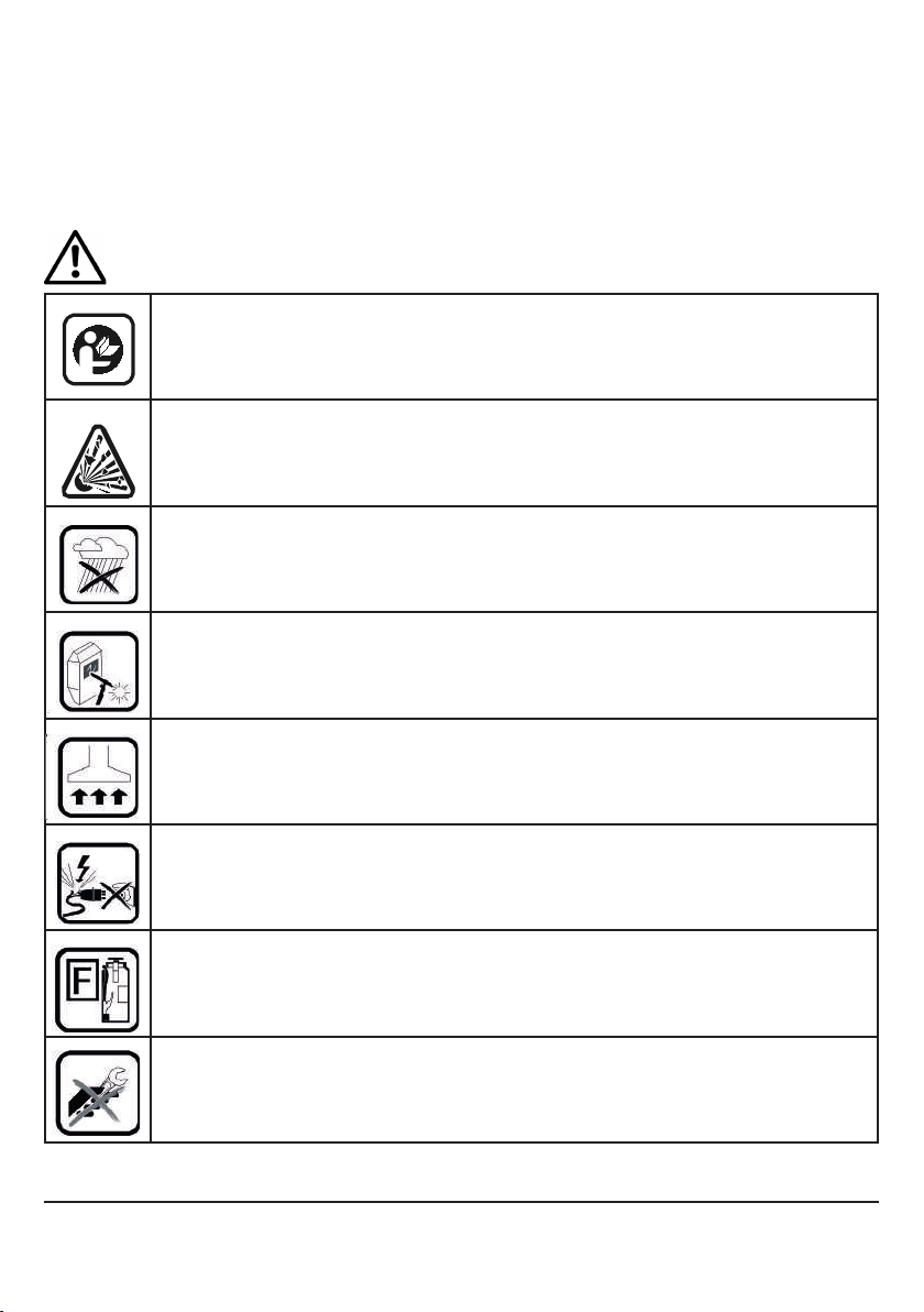
WARNING: The device cannot be used for the purpose of pipe defrosting! Information
contained on the icons placed on the device:
Use and maintenance of welding equipment may be dangerous. The user must
observe health and safety rules and regulations. Welding and cutting machines
may be used only by qualied personnel. Follow your local rules and regulations
on working with that type of devices and prevention of accidents.
Prior to starting your work remove all ammables from the welding area. Welding
inside tanks previously used as ammable liquids storage is forbidden. Place all
combustible materials away from welding spatter.
Do not expose the device to rain or water vapour and do not spray water over it.
Do not weld without proper eye protection. Pay attention to providing safety for
bystanders against welding radiation.
Use ventilation and lters in order to remove welding fumes from the work site.
Use individual lters if the ltering/ventilation system does not operate correctly or
is not available.
Stop your work immediately after nding damage to the power cords. Do not to-
uch the damaged cords. Prior a repair or maintenance disconnect the device from
power source. Never use the device with damaged power cords.
Keep a re extinguisher close to the welding location. After nishing work
check the work station against re hazards.
Never try to x a damaged gas reducer on your own. In case of malfunction repla-
ce the reducer to a fully functional one.

User Manual
Version 1.0 of 07.08.2019
Original manual
PONTIG 210 DC MOST -4-
WARNING: The following user manual should be read prior installing and starting the
device. OSH manual should be known to every welder and employee
responsible for equipment maintenance.
Attention!
Commissioning and normal operation are possible only after reading the carefully reading fol-
lowing manual. Arc welding requires compliance with the requirements for electric arc welding
and re regulations. The welder should be supplied with protective clothing and equipment in
accordance
with current regulations. It is necessary to use a set of personal protective equipment (PPE)
according to provisions of the Council Directive 89/686/EEC. The protection measures inclu-
des: welding mask with protective lter, welding gloves, apron, welding clothing, leather shoes.
Despite the high technical standard of the device, the personnel should represent considerable
discipline in approach to health and safety requirements to protect against harmful and health
hazardous factors developed from welding technology.
OPERATING CONDITIONS
This device can operate under severe conditions. It is however important to apply simple pre-
ventive measures to ensure long and reliable work:
- do not place or use this device on an inclined surface (of more than 15º),
- do not use the device for pipe defrosting,
- this device must be located within a free circulation, of clean air without restrictions of airow
to and from the fan, when the device is connected to electric network, do not cover it (with
paper or cloth)
- minimize the amount of dirt and dust that can get into the device,
- device housing has an IP21S protection. Keep it dry and do not place on wet surfaces
or in a puddle,
- do not use the device for welding the tanks previously used for storing ammable substances.
ENVIRONMENTAL CONDITIONS
Range of air temperatures for
- operation from -10ºC to +40ºC
- storage and transportation from -25ºC to +55ºC
- air relative humidity: up to 50% at +40ºC; to 90% at +20ºC.
GASES AND FUMES
TIG and MMA welding modes produce harmful gases and fumes containing ozone and hydro-
gen as well as oxides or metal particles. Therefore, the welding work station should be tted
with very good ventilation (dust and smoke extraction or airy location). Metal surfaces intended
for welding should be free from chemical contamination, especially degreasers (solvents) that
decompose during welding process and produce toxic gases. Welding of galvanized, cadmium-
-coated or chromium-plated parts is permitted only when a suction and ltering device is tted,
and with introduction of fresh air to the welding work station.

User Manual
Version 1.0 of 07.08.2019
Original manual
PONTIG 210 DC MOST -5-
RADIATION
Ultraviolet emission radiated when welding is harmful to eyesight and skin. Therefore a welding
mask with protective lters is required. Welding work station should meet certain requirements
and include:
- adequate lighting system,
- xed or movable protection screens, governing bystanders against radiation eects,
- placed in a room with appropriate wall colour (absorption of UV radiation)
FIRE PROTECTION
Welding work station should be located at a safe distance from ammables placed especially
on the oor or walls. All ammables need re protection against hot metal drops. It is
recommended to t the work station with re blankets and re extinguishers.
PROTECTION AGAINST ELECTRIC SHOCK
It is unacceptable to connect the device to an improper installation or to an installation
with unveried zeroing eciency. Removing the outer covers when
the device is connected to electric network, as well as using the device with removed covers.
IS PROHIBITED. It is not allowed to work on a suspended device e.g. using a gantry or a
crane. Maintenance and repair works should be carried out by authorized personnel
in compliance with the applicable safety conditions.
2. Maintenance
ATTENTION: In order to carry out any repair or maintenance activity, it is
recommended to contact your nearest technical support of RYWAL-RHC (a list of
authorized service shops is available on the last page of the manual).
In the event of noticing any damage, the welder should stop working, disconnect the device
from power supply and report it to direct supervisor or appropriate service - RYWAL-RHC
technical support.
General maintenance (daily)
- check the condition of cables and connections, replace if necessary,
- check condition of welding torch and connection with welding cable, replace if necessary,
- check condition and operation of the cooling fan; keep the cooling air inlet and outlet openings
clean,
- keep the device clean.
Periodic maintenance (at least every 3 months)
Periodic maintenance frequency can be increased depending on working conditions
and the intensity of use.
The scope of maintenance:
- using a stream of dry air (at low pressure) remove the dust from the outer parts of the casing
and from inside of the welding device,

User Manual
Version 1.0 of 07.08.2019
Original manual
PONTIG 210 DC MOST -6-
- check and tighten all the screws,
- check the state of all electrical contacts and repair if necessary.
WARNING: Device must be disconnected from electrical network before performing
any maintenance and service work. After each repair, perform respective
check to ensure safe use.
Mandatory device checks
According to the Labour Code provisions: „All responsibility for the safe use of machinery and
equipment shall be borne by the owner.” This results in the obligation to perform periodic and
post-repair checks and inspections of equipment.
Periodic tests are carried out at least once a year (legal basis EN ISO 17662 clause 4.2), and
post-repair tests after each repair that restored welding functionality (legal basis: EN 60974-4
clause 4.6).
All above services re performed by the technical support of RYWAL-RHC.
3. Technical description
The PONTIG 210 DC device is an inverter welding rectier for TIG welding in an argon shield
(arc ignition by HF ionizer) or an MMA coated electrode (Stick). The device has excellent we-
lding properties and has a wide range of applications. It may be used for welding:
a/ MMA electrode welding - direct current (DC) Recommended electrode diameter: 2.0 - 4.0
mm. Electrodes with a rutile or basic coating (open circuit voltage DC Uₒ = 65V), for steel and
stainless steel, b/ TIG DC method Arc ignition by an ionizer, automatically opened gas electro-
valve.
For stainless steel and steel welding a tungsten electrode is recommended with a diameter 1.6
or 2.4 mm, It is recommended to weld using continuous or pulsating current.
The device is protected against overheating by a thermal sensor. It is made in accordance with
the EN 60974-1 Standard, „Arc welding equipment. Part 1: Welding power
sources”.
4. Installation and use
- The user is responsible for connecting the device in accordance with the manufacturer
instructions. In the event of electromagnetic interference, the user should rectify the cause, if
necessary, with the knowledge of the manufacturer.
- Before using the device, the welder should estimate the possible impact of disturbances on
the environment, in particular the presence of persons with pacemakers or hearing aids.
- Work with a power generator is acceptable, but it must meet certain requirements. It is recom-
mended to use a unit with a power of min. 8 kVA with asynchronous generator. If the aggregate
does not provide adequate power, this results in lowering the arc parameters or turning o the
device.

User Manual
Version 1.0 of 07.08.2019
Original manual
PONTIG 210 DC MOST -7-
Parameter Unit Value
Electrical power supply V/Hz 1x230/50-60
Power tolerance % +15/-15
Welding current range A TIG: 10-200
MMA: 10-180
Welding current set point Smooth
Overload protection A 16 (delayed)
Work cycle
MMA DC A/%
180/35
137/60
106/100
Work cycle
TIG DC A/%
200/35
153/60
118/100
MMA electrode diameter mm 2,0-4,0
Sockets for connecting
welding cable
35/50 (large)
Power factor cos 0,7
Power consumption kW 8,2 (MMA)
6,0 (TIG)
Eciency % 85
Plug Schuko 16A
Insulation class F
Protection class IP 21S
Standard EN 60974-1
CE Ma
Dimensions mm 432x167x312
Weight kg 8,2
(11 kg carton of accessories)
Catalogue no. 52 00 005423
5. Technical data and device completion
Table 1: Technical data PONTIG 210 DC MOST.
Device assembly:
PONTIG 210 DC is delivered in a cardboard box with gas hoses,
mass cables and MMA welding electrode. TIG torch is an optional accessory - see Accessories.
Accessories:
TIG Torch 26 Most 4m(Pontig 210 /202) 56 01 032622
TIG Torch 26 Most 8m (Pontig 210/202) 56 01 032624
Welding trolley WUS HD 50 03 003942

User Manual
Version 1.0 of 07.08.2019
Original manual
PONTIG 210 DC MOST -8-
6. Device construction
Figure 1: PONTIG 210 DC MOST device construction
1. ON/OFF switch (rear side)
2. Gas connection (rear side)
3. Top handle
4. Control panel (see section 7)
5. Current socket (+)
6. TIG torch-controlled socket
7. TIG torch gas connection
8. Current socket (-)
9. Power cable with plug (device rear side)
8
9
2
1
7
3
6
5
4

User Manual
Version 1.0 of 07.08.2019
Original manual
PONTIG 210 DC MOST -9-
7. Pontig 210 DC Control panel
1. Parameter display
2. Parameter selection button
3. Operating mode selection button on the TIG torch
4. Welding parameter adjustment knob
5. Welding method selection button
Selection of welding method:
6. TIG pulse indicator
7. TIG DC indicator
8. MMA indicator
Selection of operation mode
from the TIG torch
9. 2T indicator (2-stroke mode)
10. 4T indicator (4-stroke mode)
11. Spot welding indicator

User Manual
Version 1.0 of 07.08.2019
Original manual
PONTIG 210 DC MOST -10-
12. I2 TIG background current indicator
13. I1 TIG/MMA welding current indicator
14. TIG current raise time indicator (upslope time)
15. TIG initial current indicator
16. TIG gas ow indicator
17. TIG pulse time factor indicator
18. TIG pulse frequency indicator
19. Spot welding time / HotStart arc ignition indicator
20. ArcForce function indicator
21. TIG gas post-ow indicator
22. TIG nal current indicator
23. TIG current drop time indicator (downslope time)
24. Thermal protection indicator
25. Output voltage indicator
Figure 2: Control panel and indicator description
Tabla de contenidos
Otros manuales de Sistema de soldadura de Most

Most
Most Fanmig 201 LCD Manual de usuario

Most
Most Fanmig 322 mobil Pulse Manual de usuario

Most
Most FANMIG 280-4N Minor Manual de usuario

Most
Most Fanmig J5 MOST Manual de usuario

Most
Most PONTE 201 PRO MOST Manual de usuario

Most
Most PONTIG 202 AC/DC MOST Manual de usuario

Most
Most Fanmig 522i Pulse Manual de usuario

Most
Most MasterCut 120 CNC Manual de usuario
Manuales populares de Sistema de soldadura de otras marcas


TAFA
TAFA 30*8B35 Manual de usuario

Lincoln Electric
Lincoln Electric INVERTEC V350-PRO CE Manual de usuario

ESAB
ESAB Buddy Arc 145 Manual de usuario

CIGWELD
CIGWELD 636804 Guía rápida

Red-D-Arc
Red-D-Arc DC-400 Manual de usuario

Hobart Welding Products
Hobart Welding Products Spool Gun DP 3035-10 Manual de usuario


