Monacor CARPOWER CAP-20HEX Manual de usuario
Power-Kondensator
1Verwendungsmöglichkeiten
Der Power-Kondensator wird in Kraftfahrzeugen zur
Stabilisierung der 12-V-Versorgungsspannung für
Hochleistungsendstufen eingesetzt und gleicht die
Belastung der Bordspannung bei besonders kräftigen,
tiefen Bässen aus. Dadurch ergibt sich eine höhere
Verstärkerleistung und eine deutliche Klangverbesse-
rung.
2Sicherheitshinweise
Der Kondensator entspricht der Kfz-Richtlinie und ist
unter der Nummer e13 021192 geprüft worden.
●Der Anschluss des Kondensators an das 12-V-Netz
darf nur durch qualifiziertes Fachpersonal erfolgen.
Dabei ist besondere Sorgfalt geboten. Bei Kurz-
schlüssen können gefährlich hohe Ströme fließen.
●Der Kondensator muss fest und fachgerecht an
einer mechanisch stabilen Stelle im Fahrzeug mon-
tiert werden, damit er sich nicht löst und zu einem
gefährlichen Geschoss wird.
●Schützen Sie den Kondensator vor Feuchtigkeit und
extremen Temperaturen (zulässiger Einsatztempe-
raturbereich
-
20°C bis +60°C).
●Für die Reinigung nur ein weiches, trockenes Tuch
verwenden, auf keinen Fall Chemikalien oder Was-
ser.
●Wird der Kondensator zweckentfremdet, nicht rich-
tig angeschlossen oder nicht fachgerecht repariert,
kann keine Garantie für den Kondensator und keine
Haftung für daraus resultierende Sach- oder Perso-
nenschäden übernommen werden.
●Soll der Kondensator endgültig aus dem Betrieb
genommen werden, übergeben Sie ihn zur umwelt-
gerechten Entsorgung einem örtlichen Recycling-
betrieb.
ADJUST
(+)
(
-
)
1
➀
Copyright©by MONACOR INTERNATIONAL GmbH & Co. KG, Bremen, Germany. All rights reserved. www.monacor.com A-0124.99.01.08.2003
HIGH TECH
POWER CAPACITOR
®
BRIDGE MODE
SPEAKERS
L+
FUSE FUSE FUSE FUSE
GROUND POWER
RMT BATT
R+L
-
R
-
ADJUST
(+)
(
-
)
!
➁
BatterieMasse
Sicherung
max.
20cm
Masse
Endstufe
CAP-20HEX
2
3
4
5
6
7
CAP-20HEX
Best.-Nr. 14.2230
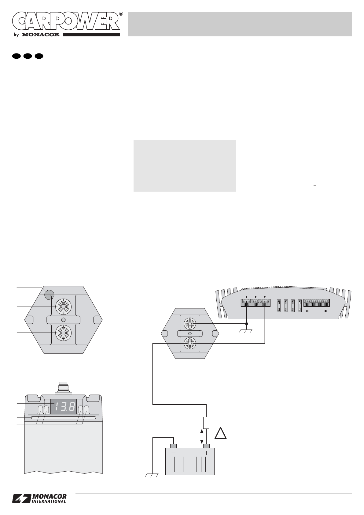
D A CH 3Montage und Anschluss
Die Kabel zwischen dem Kondensator und der End-
stufe sollten möglichst kurz sein und einen großen
Querschnitt* aufweisen. Die Kabel so verlegen, dass
deren Isolierung nicht beschädigt werden kann.
1) Den Kondensator möglichst nahe der Endstufe mit
den beiliegenden Halterungen an einer mecha-
nisch stabilen Stelle fest anschrauben.
2) Der Anschluss ist in Abb. 2 dargestellt. Die Minus-
klemme (4) des Kondensators über ein Kabel mit
der Masse des Fahrzeugs verbinden. Zur Ver-
meidung einer Masseschleife die gleiche Stelle
wählen, an der auch die Endstufe an Masse liegt.
3) An den Pluspol der Autobatterie ein Kabel mit aus-
reichend großem Querschnitt* anschließen.
Nach dem Aufladevorgang, wenn der Anzeigewert
des Digitalvoltmeters (5) nicht weiter steigt, das
Pluskabel der Batterie direkt an die Plusklemme (2)
des Kondensators anschließen. Von der Plusklem-
me des Kondensators ein weiteres Kabel zum Ver-
sorgungsspannungsanschluss der Endstufe führen.
4Anzeigeelemente und Signalgeber
1akustischer Signalgeber: EinAlarmton ertönt, wenn
die Plus- und Minusklemmen am Kondensator ver-
tauscht angeschlossen werden. Bei Unterspan-
nung (z.B. beim Aufladen) ertönt ein Signalton.
5Digitalvoltmeter: zeigt die anliegende Spannung
an.
6Neon-Leuchtring: zündet ab ca. 12,5V.
7LEDs: blinken, wenn der Kondensator geladen
oder entladen wird.
4.1 Feineinstellung der Spannungsanzeige
Werden mehrere Kondensatoren parallel geschaltet,
kann durch Toleranzen jeder einzelne Kondensator
eine etwas andere Spannung anzeigen. Mit dem
Trimmpoti ADJUST (3) die Kondensatoren auf eine
gleiche Spannungsanzeige einstellen. Dabei sollte ein
präzises Digitalvoltmeter zur Hilfe genommen werden,
um die anliegende Spannung genau zu ermitteln.
5Technische Daten
Kapazität: . . . . . . . . . . . . . . . 2F
Spannungsfestigkeit: . . . . . . 22V
Abmessungen: . . . . . . . . . . . 90 x 310 x 80mm
Gewicht: . . . . . . . . . . . . . . . . 2,3kg
Anschlüsse: . . . . . . . . . . . . . 2 x Schraubklemme
Laut Angaben des Herstellers.
Änderungen vorbehalten.
Wichtig!
Zum Schutz gegen Kurzschlüsse unbedingt eine
Sicherung* in Nähe der Batterie zwischen-
schalten (siehe Abb. 2).
Beim ersten Aufladen das Pluskabel der Batterie
und den Pluspol (2) des Kondensators unbedingt
über die beiliegende Glühlampe verbinden, um
Beschädigung durch zu hohe Stromspitzen zu
vermeiden.
*siehe Montageanleitung für die Endstufe

Power Capacitor
1Applications
The power capacitor is used in vehicles for stabilizing
the 12 V supply voltage for high power amplifiers and
equalizes the load of the voltage of the car in case of
especially powerful, low bass frequencies. This results
in a higher power of the amplifier and a considerable
sound improvement.
2Safety Notes
The capacitor corresponds to the directive for motor
vehicles and has been tested under the number
e13 021192.
●The connection the capacitor to the 12V mains
must only be made by qualified, specialized person-
nel. Special care has to be taken. In case of short
circuits there may be dangerously high currents.
●The capacitor must be mounted to a mechanically
stable place in the car. It must be skilfully fixed so
that it does not work loose and turn into a dangerous
projectile.
●Protect the capacitor against humidity and exces-
sive temperatures (admissible ambient temperature
range
-
20°C to +60°C).
●For cleaning only use a dry, soft cloth, by no means
chemicals or water.
●If the capacitor is used for purposes other than orig-
inally intended, if it is not connected correctly or not
repaired in an expert way, no guarantee claims for
the capacitor and liability for resulting personal
damage or material damage can be taken over.
●If the capacitor is to be put out of operation defini-
tively, it must be disposed of in a local recycling
plant for disposal which is not harmful to the en-
vironment.
3Mounting and Connection
The cables between the capacitor and the power
amplifier should be as short as possible and show a
large cross section*. Lay the cables so that their insu-
lation may not be damaged.
1) Tightly screw the capacitor with the supplied
brackets as close as possible to the power ampli-
fier at a mechanically stable place.
2) The connection is shown in fig. 2. Connect the
negative terminal (4) of the capacitor via a cable to
the ground of the car. To avoid a ground loop,
choose the same place at which also the power
amplifier is connected to ground.
3) Connect a cable with a sufficient cross section* to
the positive pole of the car battery.
After charging, if the display value of the digital volt-
meter (5) does not increase further, connect the
positive cable of the battery directly to the positive
terminal (2) of the capacitor. Lay another cable
from the positive terminal of the capacitor to the
supply voltage connection of the power amplifier.
* see mounting instructions for the power amplifier
4Display Elements and Signal Device
1Buzzer: an alarm sounds if the positive and nega-
tive terminals at the capacitor are mixed up while
connecting. In case of undervoltage (e.g. during
charging) a signal sounds.
5Digital voltmeter: indicates the applied voltage.
6Neon ring: ignites from approx. 12.5V.
7LEDs: flash if the capacitor is charged or dis-
charged.
4.1 Fine adjustment of the voltage display
If several capacitors are connected in parallel, each
individual capacitor may indicate a slightly different
voltage due to tolerances. With the trimming potentio-
meter ADJUST (3) adjust the capacitors to the same
voltage display. A precise digital voltmeter should be
used to exactly determine the applied voltage.
5Specifications
Capacitance: . . . . . . . . . . . . 2F
Voltage stability: . . . . . . . . . . 22V
Dimensions: . . . . . . . . . . . . . 90 x 310 x 80mm
Weight: . . . . . . . . . . . . . . . . . 2.3kg
Connections: . . . . . . . . . . . . 2 x screw terminal
According to the manufacturer.
Subject to change.
Important!
As a protection against short circuits always insert
a fuse* close to the battery (see fig. 2).
For the first charging, connect in any case the
positive cable of the battery and the positive pole
(2) of the capacitor via the supplied incandescent
lamp to avoid damage due to excessive current
peaks.
ADJUST
(+)
(
-
)
1
➀
Copyright©by MONACOR INTERNATIONAL GmbH & Co. KG, Bremen, Germany. All rights reserved. www.monacor.com A-0124.99.01.08.2003
HIGH TECH
POWER CAPACITOR
GB
®
BRIDGE MODE
SPEAKERS
L+
FUSE FUSE FUSE FUSE
GROUND POWER
RMT BATT
R+L
-
R
-
ADJUST
(+)
(
-
)
!
➁
batteryground
fuse
max.
20cm
ground
power amplifier
CAP-20HEX
2
3
4
5
6
7
CAP-20HEX
Best.-Nr. 14.2230

Condensateur de
puissance
1Possibilités d’utilisation
Le condensateur de puissance est utilisé dans les
véhicules pour stabiliser la tension d’alimentation 12V
pour amplificateurs de puissance et compense la
puissance de la tension du véhicule pour des graves
profonds et particulièrement puissants. On obtient
ainsi une puissance d’amplificateur plus importante et
une amélioration sensible du son.
2Conseils d’utilisation et de sécurité
Le condensateur répond à la directive relative aux
véhicules et a été vérifié sous le numéro e13 021192.
●Le branchement du condensateur à l’alimentation
12V du véhicule ne doit être effectuée que par un
technicien habilité. Il convient d’être particulière-
ment prudent. En cas de courts-circuits, des cou-
rants élevés peuvent circuler et être dangereux.
●Le condensateur doit être monté de manière fixe et
par un technicien habilité, dans un endroit mécani-
quement stable dans le véhicule pour éviter qu’il ne
se désolidarise de son support et ne se transforme
en projectile dangereux.
●Protégez le condensateur de l’humidité et de
températures extrêmes (plage de température de
fonctionnement autorisée :
-
20°C à +60°C).
●Pour le nettoyer, utilisez uniquement un chiffon sec
et doux, en aucun cas de produits chimiques ou
d’eau.
●Nous déclinons toute responsabilité en cas de dom-
mages matériels ou corporels si le condensateur est
utilisé dans un but autre que celui pour lequel il a été
conçu, s’il n’est pas correctement branché ou s’il
n’est pas réparé par une personne habilitée ; en
outre, la garantie deviendrait caduque.
●Lorsque le condensateur est définitivement retiré du
marché, vous devez le déposer dans une usine de
recyclage de proximité pour contribuer à son élimi-
nation non polluante.
3Montage et branchement
Les cordons entre le condensateur et l’amplificateur
doivent être le plus court possible et d’une grande
section*. Placez les câbles de telle sorte que leur iso-
lation ne puisse en aucun cas être endommagée.
1) Vissez fermement le condensateur le plus près
possible de l’amplificateur avec les supports four-
nis à un endroit mécaniquement stable.
2) Le schéma 2 présente le branchement. Connectez
la borne moins (4) du condensateur via un câble, à
la masse du véhicule. Pour éviter tout bouclage de
masse, choisissez le même endroit que celui où se
trouve la masse de l’amplificateur.
3) Reliez un câble avec une section* suffisamment
grande au pôle plus de la batterie du véhicule.
Après le processus de charge, lorsque la valeur
d’affichage du voltmètre digital (5) n’augmente
plus, reliez le câble plus de la batterie directement
à la borne plus (2) du condensateur. Tirez un autre
câble de la borne plus du condensateur vers le
branchement de tension d’alimentation de l’amplifi-
cateur.
*voir notice de montage de l’amplificateur
4Eléments d’affichage et avertisseur
1Avertisseur sonore : un signal sonore retentit si les
bornes plus et moins sont inversées sur le conden-
sateur. En cas de tension inférieure (par exemple
pendant la charge), un signal sonore retentit.
5Voltmètre digital : indique la tension présente
6Anneau lumineux néon : s’allume à partir de 12,5V
environ
7LEDs : brillent si le condensateur est chargé ou
déchargé
4.1 Réglage précis de l’affichage de la tension
Si plusieurs condensateurs sont branchés en par-
allèle, chacun des condensateurs peut afficher une
autre tension, en raison des tolérances.Avec le poten-
tiomètre trimmer ADJUST (3) réglez les condensa-
teurs sur un affichage de tension similaire. Il est
recommandé d’utiliser un voltmètre digital précis pour
déterminer avec précision la tension présente.
5Caractéristiques techniques
Capacité : . . . . . . . . . . . . . . . 2 F
Tenue tension : . . . . . . . . . . 22V
Dimensions : . . . . . . . . . . . . 90 x 310 x 80mm
Poids : . . . . . . . . . . . . . . . . . 2,3kg
Branchements : . . . . . . . . . . 2 x borne à vis
D’après les données du constructeur.
Tout droit de modification réservé.
Important !
Pour protéger le câble de courts-circuits, un fusi-
ble* doit impérativement intercalé à proximité de
la batterie (voir schéma 2).
Lors de la première charge, reliez impérativement
le câble plus de la batterie et le pôle plus (2) du
condensateur via la lampe à incandescence four-
nie : vous éviterez ainsi tout dommage causé par
des pointes de courant trop importantes.
ADJUST
(+)
(
-
)
1
➀
Copyright©by MONACOR INTERNATIONAL GmbH & Co. KG, Bremen, Germany. All rights reserved. www.monacor.com A-0124.99.01.08.2003
HIGH TECH
POWER CAPACITOR
®
BRIDGE MODE
SPEAKERS
L+
FUSE FUSE FUSE FUSE
GROUND POWER
RMT BATT
R+L
-
R
-
ADJUST
(+)
(
-
)
!
➁
batteriemasse
fusible
max.
20cm
masse
amplificateur
CAP-20HEX
2
3
4
5
6
7
CAP-20HEX
Best.-Nr. 14.2230
F B CH

Condensatore di potenza
1Possibilità d’impiego
Il condensatore di potenza viene impiegato in automo-
bili per stabilizzare la tensione di alimentazione 12V
degli stadi finali ad alta potenza, e nello stesso tempo
compensa il carico sulla tensione di bordo nel caso dei
bassi molto profondi e potenti. Ne risulta una maggio-
re potenza dello stadio finale e un chiaro miglioramen-
to del suono.
2Avvertenze di sicurezza
Il condensatore è conforme alla direttiva per auto
vetture ed è stato sottoposto a prove con il numero
e13 021192.
●Il collegamento con la rete 12V deve essere ese-
guito solo da personale qualificato e con particolare
cura. Nel caso di cortocircuiti, si possono avere
delle correnti pericolosamente alte.
●Il condensatore deve essere montato bene ed a
regola d’arte in un posto meccanicamente stabile
della vettura per escludere che si possa staccare
diventando un proiettile pericoloso.
●Proteggere il condensatore dall’umidità e da tempe-
rature estreme (temperatura d’impiego ammessa
fra
-
20°C e +60°C).
●Per la pulizia usare solo un panno morbido, asciut-
to; non impiegare in nessun caso prodotti chimici o
acqua.
●Nel caso d’uso improprio, di collegamenti sbagliati o
di riparazione scorretta non si assume nessuna
garanzia e nessuna responsabilità per eventuali
danni consequenziali a persone o cose.
●Se si desidera eliminare il condensatore definitiva-
mente, consegnarlo per lo smaltimento ad un’istitu-
zione locale per il riciclaggio.
3Montaggio e collegamento
I cavi fra il condensatore e lo stadio finale dovrebbero
essere i più corti possibili e di grande sezione*. Siste-
mare i cavi in modo tale da non danneggiare l’isola-
mento.
1) Avvitare il condensatore il più vicino possibile allo
stadio finale e in un punto meccanicamente stabile,
servendosi delle staffe in dotazione.
2) La figura 2 illustra il collegamento. Collegare il mor-
setto negativo (4) del condensatore per mezzo di
un cavo con la massa della vettura. Per evitare
anelli di terra scegliere lo stesso punto in cui anche
lo stadio finale è collegato con la massa.
3) Collegare il positivo della batteria dell’auto con un
cavo di sezione sufficientemente grossa*.
Dopo la carica, se il valore del voltmetro digitale (5)
non sale più, collegare il cavo del positivo della bat-
teria direttamente con il positivo (2) del condensa-
tore. Dal morsetto positivo del condensatore porta-
re un altro cavo verso il morsetto di alimentazione
dello stadio finale.
*vedi le istruzioni di montaggio dello stadio finale
4Elementi di visualizzazione e segnala-
tore
1Segnalatore acustico: viene emesse un segnale
d’allarme se il positivo e il negativo del condensa-
tore sono stati invertiti. Nel caso di sottotensione
(p.es. durante la carica), viene emesse un segnale
acustico.
5Voltmetro digitale: indica la tensione presente.
6Anello a luce neon: si accende da 12,5V circa
7LED: lampeggiano mentre il condensatore viene
caricato o scaricato
4.1 Regolazione fine dell’indicazione della tensione
Se più condensatori sono collegati in parallelo, in
seguito a tolleranze è possibile che ogni condensato-
re indichi una tensione leggermente diversa. Con il
potenziometro ADJUST (3) si può impostare un’indi-
cazione della tensione uguale per tutti i condensatori.
In questo caso conviene servirsi di un voltmetro digi-
tale preciso per definire con esattezza la tensione pre-
sente.
5Dati tecnici
Capacità: . . . . . . . . . . . . . . . 2 F
Max. tensione ammessa: . . . 22V
Dimensioni: . . . . . . . . . . . . . 90 x 310 x 80mm
Peso: . . . . . . . . . . . . . . . . . . 2,3kg
Collegamento: . . . . . . . . . . . 2 x morsetti a vite
Dati forniti dal produttore.
Con riserva di modifiche tecniche.
Importante!
Come protezione contro i cortocircuiti inserire
assolutamente un fusibile* vicino alla batteria
(vedi fig. 2).
Per la prima carica occorre assolutamente colle-
gare il cavo positivo della batteria e il polo positivo
(2) del condensatore inserendo la lampadina in
dotazione per escludere dei danni in seguito a
picchi troppo alti di corrente.
ADJUST
(+)
(
-
)
1
➀
Copyright©by MONACOR INTERNATIONAL GmbH & Co. KG, Bremen, Germany. All rights reserved. www.monacor.com A-0124.99.01.08.2003
HIGH TECH
POWER CAPACITOR
®
BRIDGE MODE
SPEAKERS
L+
FUSE FUSE FUSE FUSE
GROUND POWER
RMT BATT
R+L
-
R
-
ADJUST
(+)
(
-
)
!
➁
batteriamassa
fusibile
max.
20cm
massa
stadio finale
CAP-20HEX
2
3
4
5
6
7
CAP-20HEX
Best.-Nr. 14.2230
I

Condensador de potencia
1Posibilidades de utilización
El condensador de potencia se utiliza en vehículos
para estabilizar la tensión de alimentación 12V para
amplificadores de alta potencia y compensa la carga
de la tensión del vehículo para los graves profundos y
particularmente potentes. Obtenemos así una poten-
cia de amplificadores más importantes y una mejora
sensible del sonido.
2Consejos de utilización y de seguridad
El condensador cumple la directiva relativa con los ve-
hículos y está verificada bajo el número e13 021192.
●La conexión del condensador a la alimentación 12V
del vehículo debe efectuarse solo por un técnico
habilitado. Conviene estar particularmente pruden-
te. En caso de cortocircuitos, corrientes elevadas
pueden circular y ser peligrosas.
●El condensador debe instalarse de manera fija y por
un técnico habilitado, en un lugar mecánicamente
estable en el vehículo para evitar que no se des-
atornille de su soporte y no se transforme en pro-
yectil peligroso.
●Protéjelo el condensador de la humedad y de tem-
peraturas extremas (temperatura de funcionamien-
tos autorizada:
-
20°C a +60°C).
●Para limpiarlo, utilice únicamente un trapo seco y
suave, en ningún caso de productos químicos o
agua.
●Rechazamos toda responsabilidad en caso de
daños materiales o corporales si el condensador se
utiliza en otro fin para el cual ha sido fabricado, si no
está correctamente conectado o reparado por una
persona habilitada y por estos motivos el aparato
carecería de todo tipo de garantía.
●Cuando el condensador está definitivamente saca-
do del servicio, debe depositarlo en una fábrica de
reciclaje a proximidad para contribuir a una elimina-
ción no contaminante.
3Montaje y conexión
Los cables entre el condensador y el amplificador
deberían ser lo más corto posible y de una grande
sección*. Ponga los cables de manera que el aisla-
miento no pueda en ningún caso dañarse.
1) Atornille fuertemente el condensador lo más cerca
posible del amplificador con los soportes entre-
gados en un lugar mecánicamente estable.
2) El esquema 2 presenta la conexión. Conecte el
borne negativo (4) del condensador vía un cable,
con la masa del vehículo. Para evitar todo bucle de
masa, elija el mismo lugar en el cual se encuentra
la masa del amplificador.
3) Conecte un cable con una sección* suficientemen-
te grande al polo positivo de la batería del vehículo.
Después del proceso de carga, cuando el valor del
voltímetro digital (5) no aumenta más, conecte el
cable positivo de la batería directamente al borne
positivo (2) del condensador. Tire otro cable del
borne positivo del condensador hacia la conexión
de tensión de alimentación del amplificador.
*vea manual de montaje del amplificador
4Elementos de visualización y señal
1Señal sonora: una señal sonora suena si los bor-
nes positivos y negativos están invertidos en el
condensador. En caso de tensión inferior (p.ej.
durante la carga), una señal sonora suena.
5Voltímetro digital: indica la tensión presenta.
6Anilla luminosa: se enciende a partir de 12,5V más
o menos.
7LEDs: brillan si el condensador está cargado o
descargado.
4.1 Reglaje preciso de la visualización de la tensión
Si varios condensadores están conectados en parale-
lo, cada condensador puede visualizar una tensión
diferente, según las tolerancias. Con el potenciómetro
ADJUST (3) regule los condensadores en una visua-
lización de tensión similar. Un voltímetro digital preci-
so podría utilizarse para determinar con precisión la
tensión presente.
5Características técnicas
Capacidad: . . . . . . . . . . . . . 2 F
Tensión máx. posible: . . . . . 22V
Dimensiones: . . . . . . . . . . . . 90 x 310 x 80mm
Peso: . . . . . . . . . . . . . . . . . . 2,3kg
Conexiones: . . . . . . . . . . . . . 2 x borne con tuerca
Según datos del fabricante.
Nos reservamos el derecho de modificación.
¡Importante!
Para proteger de los cortocircuitos, un fusible*
debe imperativamente estar intercalado a proxi-
midad de la batería (vea esquema 2).
Durante la primera carga, conecte imperativa-
mente el cable positivo de la batería y el polo
positivo (2) del condensador vía la lámpara incan-
descente entregada: evitará así todos daños cau-
sados por puntas de corriente demasiadas impor-
tantes.
ADJUST
(+)
(
-
)
1
➀
Copyright©by MONACOR INTERNATIONAL GmbH & Co. KG, Bremen, Germany. All rights reserved. www.monacor.com A-0124.99.01.08.2003
HIGH TECH
POWER CAPACITOR
®
BRIDGE MODE
SPEAKERS
L+
FUSE FUSE FUSE FUSE
GROUND POWER
RMT BATT
R+L
-
R
-
ADJUST
(+)
(
-
)
!
➁
bateríamasa
fusible
max.
20cm
masa
amplificador
CAP-20HEX
2
3
4
5
6
7
CAP-20HEX
Best.-Nr. 14.2230
E

Kondensator Mocy
1 Zastosowanie
Kondensator mocy stosuje się w pojazdach do stabi-
lizacji napięcia źródła 12 V przy zastosowaniu wzmac-
niaczy wysokiej mocy oraz do wyrównania spadków
napięcia spowodowanych wyjątkowo silnymi dźwiękami
o niskiej częstotliwości. Dzięki temu moc wzmacniacza
jest większa oraz poprawia się wyraźnie jakość dźwięku.
2 Informacje Dotyczące Bezpieczeństwa
Kondensator odpowiada wytycznym dla pojazdów me-
chanicznych. Był testowany pod numerem e13 021192.
●
Podłączanie kondensatora do źródła 12 V może być
dokonywane jedynie przez wykwalifikowanych spec-
jalistów. Należy zachować szczególną ostrożność.
W przypadku krótkich spięć mogą wystąpić niebez-
piecznie wysokie napięcia.
●
Kondensator musi być przymocowany do stabilnego
mechanicznie miejsca w pojeździe. Musi być solidnie
przytwierdzony tak, aby nie mógł się swobodnie
poruszać, przez co mógłby stwarzasć niebezpie-
czeństwo podczas jazdy.
●
Urządzenie należy chronić przed wilgocią i nadmierny-
mi temperaturami (dopuszczalny zakres temperatury
otoczenia pracy wynosi od
-
20 °C do +60 °C).
●
Do czyszczenia należy używać jedynie czystych i
suchych kawałków materiału. Nie używać środków
chemicznych, ani wody.
●
Dostawca oraz producent nie ponoszą odpowiedzial-
ności za ewentualnie wynikłe szkody materialne lub
uszczerbki na zdrowiu, jeśli urządzenie było używane
niezgodnie z przeznaczeniem, zostało niepoprawnie
zainstalowane lub obsługiwane oraz było poddawane
naprawom przez nieautoryzowany personel.
●
Jeśli urządzenie nie będzie już nigdy więcej używane
wskazane jest przekazanie go do miejsca utylizacji
odpadów, aby zostało zutylizowane bez szkody dla
środowiska.
3Montaż i Podłączanie
Przewody łączące kondensator oraz wzmacniacz
powinny być możliwie najkrótsze oraz powinny być
grube w przekroju*. Powinny być położone w ten
sposób, aby ich izolacja nie mogła ulec uszkodzeniu.
1) Należy mocno zamocować kondensator za pomocą
dołączonych obejm, możliwie blisko wzmacniacza
mocy w stabilnym mechanicznie miejscu.
2) Sposób podłączenia pokazany jest na rys. 2. Biegun
ujemny należy za pomocą przewodu połączyć z
masą pojazdu. W celu uniknięcia pętli masy należy
wybrać to samo miejsce połączenia, w którym
podłączony do masy jest również wzmacniacz.
3) Przewód o odpowiednim, dopuszczalnym przekro-
ju* do dodatniego bieguna akumulatora.
Po naładowaniu kiedy wartość wyświetlana na
wskaźniku napięcia (5) nie wzrasta, należy podłączyć
przewód akumulatora bezpośrednio do zacisku bie-
guna dodatniego kondensatora (2). Przewód przy-
mocowany do kolejnego zacisku bieguna dodatnie-
go kondensatora do wejścia zasilania wzmacniacza
mocy.
*patrz instrukcja wzmacniacza mocy
4Elementy Wskazujące oraz Sygnalizacja
Dźwiękowa
1Buzzer: Sygnał alarmu dźwiękowego rozbrzmiewa,
kiedy dodatni oraz ujemny biegun kondensatora są
zamienione podczas podłączania. W przypadku
nadmiernego zasilania (np.: podczas ładowania)
wydobywa się dźwięk.
5Woltomierz cyfrowy: wskazuje wysokość zastosowa-
nego napięcia.
6Pierścień świecący: zapala się przy około 12,5 V.
7Diody świecące: migają, kiedy kondensator jest
ładowany lub rozładowywany.
4.1
Dostrajanie wyświetlania napięcia
Jeżeli kilka kondensatorów jest połączonych szeregowo,
każdy z nich może wskazywać nieco inne napięcie
w związku ich tolerancją. Za pomocą potencjometru
ADJUST (3) należy ustawić kondensatory tak, aby
wyświetlana była identyczna wartość stosowanego
napięcia. W celu ustalenia rzeczywistego stosowanego
napięcia należy użyć precyzyjnego woltomierza cyfro-
wego.
5 Dane Techniczne
Pojemność: . . . . . . . . . . . . . . 2 F
Stabilizacja napięcia: . . . . . . . 22 V
Wymiary: . . . . . . . . . . . . . . . . . Ø 90 x 310 x 80 mm
Waga: . . . . . . . . . . . . . . . . . . . 2,3 kg
Złącza: . . . . . . . . . . . . . . . . . . 2 terminale śrubowe
Zgodnie z danymi producenta.
Może ulec zmianie.
Ważne!
W celu zapobiegnięcia spięciom należy umieścić
bezpiecznik w niewielkiej odległości od akumulato-
ra (patrz rys. 2).
Przed pierwszym naładowaniem, koniecznie należy
połączyć dodatni biegun akumulatora oraz dodatni
biegun kondensatora (2) poprzez dołączoną do
zestawu żarówkę w celu uniknięcia uszkodzeń spo-
wodowanych nadmiernym napięciem chwilowym.
ADJUST
(+)
(
-
)
1
➀
Copyright©by MONACOR INTERNATIONAL GmbH & Co. KG, Bremen, Germany. All rights reserved. www.monacor.com A-0124.99.01.08.2003
HIGH TECH
POWER CAPACITOR
®
BRIDGE MODE
SPEAKERS
L+
FUSE FUSE FUSE FUSE
GROUND POWER
RMT BATT
R+L
-
R
-
ADJUST
(+)
(
-
)
!
➁
akumulatormasa
bezpiecznik
max.
20cm
masa
wzmacniacz mocy
CAP-20HEX
2
3
4
5
6
7
CAP-20HEX
Best.-Nr. 14.2230
PL
Este manual sirve para los siguientes modelos
1
Tabla de contenidos
Idiomas:
Otros manuales de Accesorios para automóviles de Monacor

Monacor
Monacor Carpower CAP-20 Manual de usuario

Monacor
Monacor Carpower HPB-450 Manual de usuario

Monacor
Monacor Carpower FGA-22HQ Manual de usuario

Monacor
Monacor CARPOWER CAP-12XHQ Manual de usuario

Monacor
Monacor Carpower CAP-10T Manual de usuario

Monacor
Monacor CARPOWER CAP-12LED Manual de usuario

Monacor
Monacor CARPOWER 14.2110 Manual de usuario

Monacor
Monacor Carpower ENF-30 Manual de usuario

Monacor
Monacor Power Concept CPS-500 Manual de usuario


