MOGAS Watson Series Manual de usuario

Installation, Operation
and Maintenance Manual
PREPARE THE VALVE FOR
INSTALLATION
INSTALL THE VALVE
PROPERLY
MAINTAIN THE VALVE FOR
OPTIMAL OPERATION
AND PERFORMANCE
for the
MOGAS Watson Series Ball Valve

© Copyright 03/31/2021 MOGAS Industries, Inc. www.mogas.com
2
All MOGAS valves operate counter-clockwise to open, clockwise to close.
MOGAS valves are supplied in a variety of operator configurations based
upon customer requirements, and may be operated by
• manual actuation (handlever) • pneumatic actuation
• worm gear actuation (handwheel) • hydraulic actuation
Each of these operator configurations may be installed and tested prior to
shipping, or shipped separately, depending on customer requirements.
Some valves are supplied with a bare stem or stem adaptor kits to
accommodate a variety of manual or actuated operators.
Please note the configuration of each individual valve and proceed with any
necessary operator adaption procedures prior to installing the valve. CLOSE
OPEN
Sequential procedure
required to perform operation.
Bold numbers correspond
with items shown in the Valve
Item Reference Number
sections.
Warning statement
to prevent unwanted
consequence.
Note(s) to support
procedure.
All information within this manual is relevant to the safe and proper
care of your MOGAS ball valve. Please understand the following
examples of instructional information:
General information or
an alternate / variation
procedure.
Read Before Installing Valve
How to Read this Manual
Note:
The normal direction of ow is from the higher pressure end (upstream)
to lower pressure end when the valve is closed.
CAUTION!
Ensure key length provides and maintains full
engagement.
THIS WILL AFFECT THE VALVE WARRANTY.
!
PRE-INSTALLATION STORAGE
Valves shall remain stored in their shipping crates
with the lids secured.
INSTALL STEM ADAPTOR
Align stem adaptor 13 so the keyways on stem
adaptor correspond with the keys 6on stem 5.
5

© Copyright 03/31/2021 MOGAS Industries, Inc. www.mogas.com 3
VALVE ITEM REFERENCE NUMBER ..................................4
TRANSPORT AND STORAGE ........................................6
PRE-INSTALLATION ...............................................7
INSTALLATION ...................................................8
OPERATION.....................................................10
MAINTENANCE....................................................... 11
REPLACE BALL & SEAT ...........................................12
REPLACE STEM PACKING .........................................13
DISASSEMBLY...................................................17
RE-ASSEMBLY ..................................................23
LOCATE VALVE INFORMATION .....................................31
RETURN MERCHANDISE AUTHORIZATIONS (RMA) ....................32
SERVICE CONTACT ..............................................32
Contents

© Copyright 03/31/2021 MOGAS Industries, Inc. www.mogas.com
4
Valve Part Reference Number
Item Description
01 Ball
02 Seat
03 Seat Ring
04 Body
05 End Connect
06 Body Gasket, Spiral Wound
07 Stem
08 Stem Seal
09 Thruster, Gland Flange
10 Gland Flange
11 Ring, Stem Packing 1
12 Stud, Body
13 Nut, Body
14 Stud, Gland
15 Nut, Gland
1Quantity varies with valve size
08
12
01
02
07
03
02 03
06
05
13
04
11
09
10
14
15
Valve Item Reference Number
Manual Adaption (Handlever)

© Copyright 03/31/2021 MOGAS Industries, Inc. www.mogas.com 5
THIS PAGE INTENTIONALLY LEFT BLANK.

© Copyright 03/31/2021 MOGAS Industries, Inc. www.mogas.com
6
These procedures outline the general requirements for
storage of MOGAS valves.
TRANSPORT
For export shipping, valves will be shipped in sea-
worthy, export-packed, plastic-lined wooden crates.
Upon arrival at the site, inspect the general condition
of the valve (and actuator, if supplied) for any potential
shipping damage.
PRE-INSTALLATION STORAGE
Valves shall remain stored in their shipping crates, or
on their pallets, with the lids secured.
Valves are shipped with corrosion-resistant paint
and desiccant dries (dryer bags) for storage up to six
months.
For long-term storage, the machined internal parts of
carbon and low alloy steel valves should be sprayed
with a rust preventative.
Keep all protective covers and plastic liners in place.
REMOVING VALVE FROM SERVICE
Before the valve is removed from the line, it should be
placed in the partially open position to relieve trapped
pressure and prevent further internal damage to valve
components.
Do not place the valve in the fully open position until it
has been cleaned of service debris in the next step.
The valve should be placed in a vertical position, or
raised at an angle. The bore of the valve should be
either steamed cleaned or power washed to remove
slurry and debris.
Rotate the valve to the fully open position to drain
and dry. A petroleum-based rust inhibitor should be
applied through the bore of the valve immediately
after the valve is dry.
Flange protectors need to be secured to each end of
the valve to prevent any foreign debris from entering
the valve. It is recommended to place desiccant dryer
bags inside the valve before storage.
The valve should be stored in the vertical position, out
of the weather (inside), until repairs can be made.
Transport and Storage

© Copyright 03/31/2021 MOGAS Industries, Inc. www.mogas.com 7
REMOVE VALVE
Remove the valve (and actuator, if supplied) carefully
from the shipping crate or pallet using lifting lugs
or nylon straps around the valve body and sturdy
section of the actuator. Do not lift by the actuator
alone.
INSPECT VALVE
Inspect the general condition of the valve (and
actuator, if supplied) for any potential shipping
damage.
Review the valve manual, assembly drawing with the
bill of materials, and the actuator manual (if supplied)
shipped with the valve.
REMOVE PROTECTIVE COVERS
Remove protective covers from the valve ends.
Inspect internally for shipping debris or damage.
INSTALL OPERATOR
The valve comes configured with a handlever from
MOGAS. It should arrive pre-assembled and tested
from the factory. If already assembled, proceed to
Installation (page 8) and continue with the valve
installation.
If the valve does not have a handlever installed, you
must install the appropriate adaptor and handlever to
open and close the valve prior to valve installation.
Pre-Installation
1
2
3
4

© Copyright 03/31/2021 MOGAS Industries, Inc. www.mogas.com
8
While looking in the bore, open and close the valve.
Note:
If a choice is available, the valves should be installed with the ow of the
media from the end piece to the body.
Note:
The MOGAS Watson Series valve operates counter-clockwise to open,
clockwise to close.
VERIFY OPERATING POSITION
Verify that the ball open / closed position matches the
handlever or actuator open / closed position indicators.
Watson Series Valves are bi-directional valves and
may be installed in either direction.
Note:
Larger valves may require the actuator to be in place to rotate the ball.
Note:
Valve item numbers shown in bold correspond with items shown in the
Valve Item Reference Number section (pages 4 – 5) of this document.
CAUTION!
The actuator, if supplied, must not be re-oriented
without removal from the valve. This prevents 180°
rotation of the ball and assures the mate-lapped
ball and seat surfaces match. (Seat leakage may
occur when the ball and seat surfaces are not
matched per the engineered design.)
THIS WILL AFFECT THE VALVE WARRANTY.
!
CAUTION!
All welding / grinding debris must be thoroughly
flushed from all associated piping before valve is
installed.
THIS WILL AFFECT THE VALVE WARRANTY.
Fully OPEN position.
Fully CLOSED position.
Installation
1
!
© Copyright 03/31/2021 MOGAS Industries, Inc. www.mogas.com 9
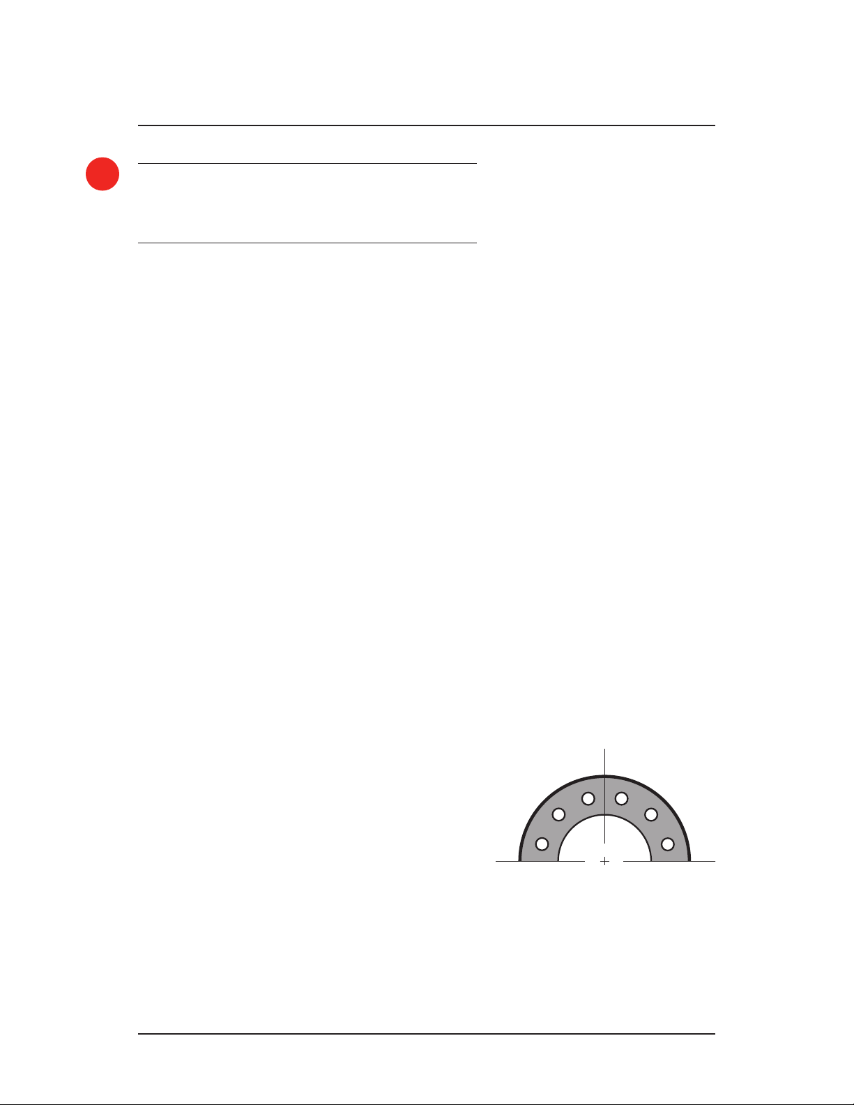
SECURE VALVE IN PLACE
For raised-face flange connections, install flange
gaskets and bolting per customer requirements. When
securing other end types, please contact MOGAS
Service for proper procedures.
Note:
MOGAS valve anges are supplied in the customary “straddle centerline”
hole orientation, unless otherwise specied.
Straddle centerline hole orientation
PROTECTING THE VALVE
The valve should be lifted with slings around the valve
and not from the stem or actuator.
Flanged raised faces should be protected at all times
prior to installation to prevent possible damage.
Note:
Actuator, gear operators and handle stops are pre-set at the factory
and should not require any further adjustments. Should the actuator or
gear operator require removal for installation, please call the factory or
authorized Service Company rst.
POSITION VALVE IN PIPING
Verify that the valve and actuator / handlever
orientation is correct.
Verify that the valve is in the open position to prevent
any damage to the ball surface from debris.
Position the valve in line with mating flanges.
Note:
Support or lift as required, using lifting lugs or nylon straps around the
valve body. Do not lift or support by the actuator alone.
3
Installation
2
4
CAUTION!
Temperature and media compatibility should be
verified prior to installation to assure the valve is
able to perform in the desired application.
!

© Copyright 03/31/2021 MOGAS Industries, Inc. www.mogas.com
10
VERIFY OPERATION
The valve should be opened and closed several times
and the packing gland nut or bolts should be checked
to make sure they are snug and applying a sealing
force on the packing prior to applying pressure.
All Watson Series ball valves are designed for on / off
services only.
To operate, turn counter-clockwise to open and
clockwise to close.
Note:
When cycling the valve open or close, make sure that the valve is fully
opened and fully closed. This wipes debris from the ball and ensures
optimal performance and long valve life.
OPEN / CLOSE
CAUTION!
Throttling with ball valves is NOT recommended.
Prolonged exposure of a portion of the ball to flow
can compromise the sealing integrity of the valve.
THIS WILL AFFECT THE VALVE WARRANTY.
Fully CLOSED position.
Fully OPEN position.
Partially OPEN position
(not recommended).
CLOSE
OPEN
Operation
!
Tabla de contenidos
Otros manuales de Unidad de control de MOGAS


Manuales populares de Unidad de control de otras marcas

Festo
Festo Compact Performance CP-FB6-E Manual de lista de piezas

Elo TouchSystems
Elo TouchSystems DMS-SA19P-EXTME Manual de usuario

JS Automation
JS Automation MPC3034A Manual de usuario

JAUDT
JAUDT SW GII 6406 Series Guía rápida

Spektrum
Spektrum Air Module System Manual de usuario

BOC Edwards
BOC Edwards Q Series Manual de usuario


