Mission 776 Manual de usuario

MISSION OWNER'S MANUAL
MISSION 776/777 UNPACKING-INSTALLATION
MODEL 776
The followin items are included with the pre-amplifier.
- Warranty card
- Owners manual
- Pre-amplifier line cord
- Banana plu
- 1 spare line fuse
MODEL 777
The followin items are included with the power amplifier.
- Warranty card
- Owners manual .
- Power amplifier line cord
- 1 spare line fuse, 2 spare output fuses
If any of the above items are not included contact your dealer or the factory.
IMPORTANT: REFER TO OPERATING INSTRUCTIONS PRIOR TO USING SYSTEM.
1 of 20
2 of 20

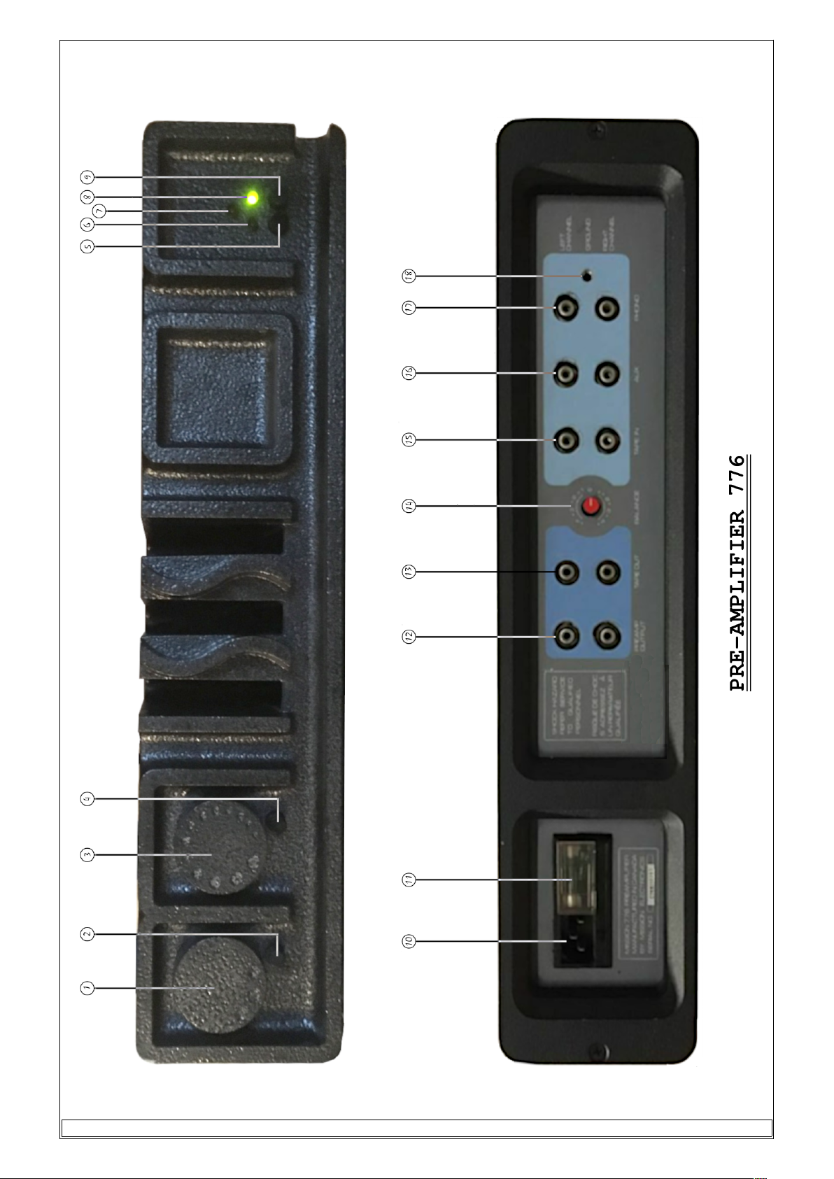
MISSION 776 OPERATING INSTRUCTIONS
(Bracketed numbers refer to panel drawin s)
FRONT PANEL
1. ON/OFF SWITCH (5) & (9)
There are two push button switches situated on the ri ht hand side of the front panel, the switch on the
extreme ri ht is desi nated "S1" (9) & beside it is "S2" (5).
With switch "S1" in the "out" position & "S2" depressed the pre-amplifier is powered from the internal
battery & all A.C. line currents are disconnected. After about 20 seconds the reen L.E.D. (7) will li ht
up indicatin the normal operatin mode of the amplifier.
When both switches are in the "out" position the amplifier is totally dead & is in its transportation mode.
With switch "S1" depressed (S2 in either position) the pre-amplifier is shut down & the battery is put on
char e.
When this is done the red L.E.D. (8) must always come on to indicate full char in mode. If the battery
requires full char in the red L.E.D. will remain on; otherwise, after a few minutes the yellow L.E.D. (6)
will illuminate indicatin trickle char e mode.
The switch over from full char e to trickle char e is done automatically.
In order to avoid the situation of havin a dischar ed battery just when you wanted to use the
amplifier, it is recommended that after normal use the pre-amplifier be switched to char e mode. The
battery can be left on char e for several days & weeks ready to be used. A fully char ed battery can
produce optimum performance for as lon as 20-30 hours of continuous use,
2. INPUT SELECTOR SWITCH (1)
The input selector switch is located at the extreme left of the front panel. The input selected is indicated by
the linin up of the indentations on the selector switch knob with the push button (2) just under it. The
middle indentation represents phono, left indentation is tape & the ri ht indentation is auxiliary input.
3. VOLUME CONTROL (3)
The volume control is the knob with pro ressively enlar ed indentations which indicate volume settin .
Its ali nment is relative to the push button (4) just under it. The volume control adjusts ain from -70db
(small indentation) up to 0dB or full ain (lar e indentation) in a stepwise fashion.
4, TAPE MONITOR SWITCH (2)
This is the push button under the input selector knob (1). Tape monitor is selected by depressin the
button.
5. MONO/STEREO SWITCH (4)
This push button is located under the volume knob (3). Mono operation is selected by depressin the
button.
3 of 20

BACK PANEL
NOTE: the top row of audio connectors represents the LEFT channel & the bottom row the RIGHT channel.
1. A.C. CONNECTOR HOUSING (10) & (11)
The detachable line cord connects to the 776 at A.C. input (10). Access to the line fuse (11) is possible only
when the line cord has been disconnected & the clear plastic window is moved aside. The fuse housin (11)
also contains a small universal volta e card that selects the correct line volta e for the country in which the
amplifier is used. See precautionary measures for correct line volta e & fuse ratin .
2. GROUND (18)
Most hi h quality turntables are manufactured with a separate roundin wire. This wire does not carry
si nal current but its provided for shieldin purposes. It is very important that the tonearm metal work
& the platter be at the same potential as the pre-amplifier chassis. If a separate roundin wire is not
provided then the shield connection is automatically done throu h the turntable interconnects -
althou h this method is not as effective as the separate wire approach.
Included with the pre-amplifier is a solder-less banana plu for connectin a separate round wire. Strip ¾
inch of insulation from the wire & unscrew plastic cap from banana plu . Push the wire throu h the small
hole of the plastic cap & into the centre hole of the metal plu so that the stripped portion of wire extends
out the side hole. Wrap the bare portion of wire around & under the exposed metal collar of the plu .
Ti hten securely the plastic cap to the banana plu . For a proper connection no bare wire will be visible.
3. PHONO INPUT (17)
The phono input will accept si nal from any movin ma net or hi h output movin coil cartrid e.
4., AUXILIARY INPUT (16)
This input will accept any line level connection. Most often this will be the output of a tuner, but it
could also be the output of a second tape recorder. This would then allow tape copyin if another
recorder was connected via tape input.
5. TAPE INPUT (5)
This input will accept any line level connection. Most often this will be the output of a tape recorder,
but it could also be the output of a television with stereo
6. BALANCE (14) IMPORTANT NOTICE
In spite of the special care taken in implementation of the balance control feature (use of the hi hest
quality switches & incorporatin the circuitry in the feedback loop, in order to further reduce any
adverse effects of this feature), our recent findin s show that this control is somewhat detrimental to
the hi h quality sonic reproduction of the 776.
Given our commitment to strai ht line philosophy & the type of associated equipment which would
invariably be used with this enre of equipment the usefulness of a balance control, at all, is questionable.
Considerin the pros & cons, Mission have decided to eliminate the balance control feature in the new
eneration of the 776 pre-amplifiers.
Dependin on the production batch which you will receive, you will find that the balance control
switch (back panel may or may not be installed. On models where the switch has already been installed
the balance control circuit has been disabled.
7. TAPE OUTPUT (13)
Interconnect cables run from here to the line input of a tape recorder to permit recordin from any source
as selected by the input selector switch. That is, phono, tuner, television, or another tape recorder.
8. PRE-AMPLIFIER OUTPUT (12)
Interconnect cables run from here to the main input of the power amplifier. This output can also feed
an equaliser which in turn would feed the input of the power amplifier.
4 of 20

SPECIFICATIONS
MISSION 776 PRE-AMPLIFIER
Input Sensitivity:
Phono: 2mV. for 1 Volt rms output
Line: 100mV for 1 Volt rms output
Input Overload at 1 kHz: Phono sta e 150m.v.
Output Level:
Nominal 1 Volt rms
Maximum 11 Volts peak
Input Impedance: 47kΩ, 150pF.
Output Impedance: 250Ω, 4µ7F.
Si nal/Noise:
Phono input 80dB "A" wei hted 20Hz-20kHz (ref. 5mV input)
Line input 95dB "CCIR" wei hted 20Hz-20kHz (ref. 200mV input)
HUM >100dB below rated output
Volume Control: Channels track within 0.2dB from 0dB down to -70dB
Distortion:
THD: <0.5% (20Hz-20kHz)
IMD: <0.5% (60Hz & 7kHz at 4:1)
TID: immeasurable
Frequency Response:
Phono: +0.2dB 20Hz~20kHz
-3dB 10Hz~50kHz
Line: -0.2dB 20Hz & 20kHz
5 of 20

MISSION 777 OPERATING INSTRUCTIONS
(Bracketed numbers refer to panel drawin s)
FRONT PANEL
1. GREEN L.E.D. (1) This li ht illuminates when the amplifier is turned on.
2. ON/OFF SWITCH (1) Self explanatory.
BACK PANEL
1. A.C. CONNECTOR HOUSING (2) & (3)
The detachable line cord connects to the 777 at A.C. input (2). Access to the line fuse (3) is possible only
when the line cord has been disconnected & the clear plastic window is moved aside. The fuse housin (3)
also contains a small universal volta e card that selects the correct line volta e for the country in which the
amplifier is used. See precautionary measures for correct line volta e & fuse ratin .
2. INPUT (6)
Interconnect cables from the pre-amplifier output connect here.
3. OUTPUT (5)
These five way heavy duty bindin posts provide different methods of connectin the speaker cable to
the amplifier. For example, when usin multi-strand heavy au e wire, divide the conductors into two
parts, pass one half throu h the hole in the terminal & wrap the remainder around the terminal post.
Ti hten plastic cap to secure wire. These terminals are also equipped to accept standard banana plu s.
4. OUTPUT FUSE (4)
Individual 3.5 ampere fast blow fuses are installed at the factory. These fuses protect the loudspeakers
from overload conditions & the amplifier from shorted speaker wires. See precautionary measures for
correct fuse ratin .
5. SOFT CLIP (7) IMPORTANT NOTICE
Due to inherently excellent clippin characteristics & ample headroom of the 777 power amplifier,
reports from the field & recommendations made by many reviewers indicate that the soft clip feature
incorporated in the amplifier is redundant.
In order to simplify & at the same time eliminate any de radation of the sonic quality which may arise
from intentional or inadvertent usa e of this feature, the soft clip switch has been completely disabled.
SPECIFICATIONS
MISSION 777 POWER AMPLIFIER
Input Sensitivity: 775 m.v. for 28.4Vrms out (100W into 8Ω)
Power:(continuous power
outputwith both channels
driven from20Hz-20kHz)
>100watts/ch. (8Ω)
>175watts/ch. (4Ω)
Slew Rate: 150 Volts/microsecond
Rise Time: 0.32 microsecond
Dampin Factor: 60 (DC-40kHz)
Open Loop Bandwidth: 230kHz
Closed Loop Bandwidth: 1.15MHz
Ne ative Feedback: 14 dB
Current Delivery: 10 amps RMS continuous 40 amps peak-to-peak instantaneous
THD: <0.2% (DC-40kHz)
Difference Frequency
Distortion: 0.05% (10 watts into 8Ω, 300Hz apart, swept from 0-200kHz)
IMD 0.05% (10 watts into 8Ω, 70Hz, fixed & swept from 0-200kHz, 4:1 ratio)
Si nal/Noise: >100dB
6 of 20

7 of 20

PRECAUTIONARY MEASURES
1. When disconnectin any piece of equipment such as a tape deck, tuner, etc. be sure to turn off
system power.
2. When chan in records, re-dialin tuner or rewindin tapes, it is recommended that the volume
control be turned down.
3. The 777 amplifier can be positioned wherever convenient, provided that some unrestricted airflow is
permitted at the top & bottom of the case. Do not place the amplifier on carpetin or any other material
that would restrict airflow. Under normal conditions the 777 will et moderately warm.
4. If it is necessary to replace a fuse, be sure to maintain the proper fuse ratin .
(A) LINE FUSE (refer to back panel drawin s (3) & (11).
JAPAN (100 Volt): ¾ ampere, slow blow, Model 776
5 ampere, slow blow, Model 777
NORTH AMERICA (120 Volt): ½ ampere, slow blow, Model 776
4 ampere, slow blow, Model 777
U.K. & EUROPE (220-240 Volt): ¼ ampere, slow blow, Model 776
2 ampere, slow blow, Model 777
When selectin a different line volta e, remove & rotate volta e card to desired volta e, then reinsert
card such that the printed volta e is clearly visible throu h the window. Chan e the fuse accordin to
the above specifications.
4. (B) OUTPUT (PROTECTION) FUSE, MODEL 777
(refer to back panel drawin (4).)
USING 8Ω SPEAKERS: 3½ or 4 ampere, fast blow
USING 4Ω SPEAKERS: 5 ampere, fast blow
5. For best possible si nal to noise fi ures Model 776 & 777 amplifiers must be connected to a properly
rounded outlet. Do not remove the third wire roundin pin on power cord plu .
6. Do not use hi h au e hi h capacitance audio cable.
SPEAKER CABLE should be 14 au e for runs of under 20 feet, otherwise use 12 au e or lower. In
either case the cable must be multi strand of pure copper. It is recommended that positive & ne ative
wires to the same speaker be separated a couple of inches for best results.
INTERCONNECT CABLE should be low capacitance with a braided shield.
8 of 20

IN CASE OF TROUBLE
SYMPTOM PROBABLE CAUSE & CURE
No sound from one or both speakers
A) Check for blown or missin . fuses in speakers & at (3)
of model 777.
B) insure that all cable connections are correct & secure to
(2), (5), (6), of 777 & (12), (13), (15), (16), (17) of 776.
C) insure that 776 batteries are fully char ed. Refer to
operatin instructions.
Low volume sound from one or both
speakers.
Check for blown fuses at (4) of model 777. These
protection fuses are wired in the feedback loop - if the
fuse blows some sound will be audible.
Hum or cracklin from one or both
speakers. This is usually caused by a faulty
round connection of a shielded
interconnectin cable.
A) Insure that there are no faulty interconnect cables.
problem
B) Insure that all interconnect cable plu s are secure
(PUSHED IN) to (12), (13), (15), (16), (17), of 776 & (6) of
777.
C) Attach all available chassis roundin wires from
turntable, tuner, tape deck, etc. to (18) of 776. Use banana
plu supplied.
D) Lon cable runs includin speaker wire can act as
antennas causin R.F.I. problems. if the above remedies do
not work then ferrite rin s must be installed on the
offendin cable. These rin s will remove the R.F.I. without
affectin sound re production. Contact your audio dealer
or the factory for further information.
Radio frequency pick-up audible from one
or both speakers.
The Mission 776/777 amplifiers have been desi ned to
reject most R.F. interference. However, R.F.I. can be a
problem dependin on where you live & the quality of
associated equipment used with the 776 or 777 amplifiers.
Music reproduction sounds hollow, certain
instruments lack definition.
Speaker POSITIVE & NEGATIVE terminals are reversed
causin frequency cancellation. Insure that the speakers
are connected properly: red (+) terminal of 777 LEFT
channel oes to red (+) terminal of LEFT speaker & black
(-) terminal of 777 LEFT channel oes to black (-) terminal
of LEFT speaker. Repeat for the RIGHT channel.
9 of 20

Mission 776 Pre-Amplifier
Mission 777 Power Amplifier
Con ratulations on your excellent choice! Your Mission pre-amplifier &/or power amplifier are precision
manufactured products & have been tested to the hi hest standards. A few minutes spent in readin
your instruction manual will ensure that you et optimum results from your system & your investment
will prove lon term.
IMPORTANT NOTES
1. Before switchin the equipment on, please ensure that it is correct for your local power supply. The
pre-amplifier & power amplifier are made in different versions for different parts of the world. Please
refer to the detailed instructions for each unit for more information.
2. Mission equipment is manufactured to the hi hest quality standards. All Mission pre-amplifiers &
amplifiers are warranted to be free of defects in materials & workmanship for a period of three years
from date of purchase.
3. Please retain packin materials. You may need them a ain for safe transport of the equipment.
INTRODUCTION
Traditionally, amplifiers are desi ned as mathematical models their characteristics measured under
steady-state conditions, & their quality jud ed by a simple set of specifications. This is inadequate for
an amplifier dynamically operatin to reproduce music. It is the dynamic behaviour of an audio
amplifier with complex interface (input/output) transducers when drivin reactive loads that hi hli hts
many obscure problems. Many "theoretically-perfect" desi ns suffer serious clippin distortions durin
musical transients; are unable to drive complex speaker loads; create poor interface with cartrid e
transducers; have inadequate power-supplies; use IC's in place of discrete components; & i nore the
detrimental effect of excessive switches & ad ets.
As for specifications, historically too much emphasis was placed on parameters such as THD or
bandwidth. This resulted in excessive use of overall feedback - enhancin specifications by reducin the
amplitude of low-order harmonics but eneratin hi h-order harmonics & listenin fati ue. A ain much
was made of bandwidth & speed of amplifiers. Fi ures of 1MHz were considered desirable. But such
fi ures do not reveal the critical ratio of power supply bandwidth to audio bandwidth; the amount of
feedback used to achieve such specifications; linearity with varyin power levels; & the respective
relationship between the closed & open-loop curves. Also, steady-state measurements i nore time
domain problems such as time & phase errors resultin in incoherent musical information.
The Mission desi ns are the result of a new look at the fundamental parameters & basic operatin
functions of an audio amplifier. Our research has been painstakin in careful evaluation & correlation of
subjective results with advanced & novel measurements.
Considerable effort was made to create inherently stable circuit desi ns capable of drivin all complex
loads & eliminatin conventional protection circuits, Zobel networks couplin capacitors, etc. The 777
achieves the unprecedented open-loop bandwidth of 230kHz resultin in 1.15MHz bandwidth with a
mere 14dB overall feedback:
Discrete components are used throu hout, switches & connectors kept to a bare minimum.
Exceptionally low output impedance power supply is utilised with some 70,000 filterin capacity.
A totally linear harmonic distortion pattern is achieved with rapidly diminishin hi h order harmonics.
Complex distortions measured over a lar e frequency band are ne li ible. The slewin rate of the 777 is
a sta erin 180 Volts per micro second, thereby eliminatin all dynamically induced distortions such as
TIM, with special attention iven to slewin behaviour at maximum output swin s.
The 777 is DC coupled throu h out, desi ned as a perfectly symmetrical class "A" amplifier, except for
the hi h technolo y H-FET output devices which operate in class "AB" mode.
10 of 20
Este manual sirve para los siguientes modelos
1
Tabla de contenidos
Otros manuales de Amplificador de Mission


