Metro DataVac MB-IP Manual de usuario

+33 (0) 450 39 08 49
Metro Fax +33 (0) 450 39 08 33
Rue de la Jonchère web www.metro-fr.com
F-74420 Boëge E-mail info@metro-fr.com
MB-IP
Master module for M-Bus network
User’s manual

Version 1.0
1. TABLE OF CONTENTS
1.TABLE OF CONTENTS ___________________________________________ 2
2.FOREWORDS __________________________________________________ 3
3.INTRODUCTION ________________________________________________ 5
3.1.PRODUCT PRESENTATION ........................................................................ 5
3.2.CARACTERISTICS ........................................................................................ 5
3.2.1.MAIN TECHNICAL CHARACTERISTICS ............................................... 5
3.2.2.DIMENSIONS AND INSTALLATION ...................................................... 6
3.2.1.CONTAINS OF THE PACKAGING ......................................................... 7
4.CONNECTORS _________________________________________________ 8
4.1.THE USB FULL-SPEED CONNECTOR ........................................................ 9
5.COMMUNICATION - ASCII PROTOCOL ____________________________ 10
5.1.NETWORK SETTING : IP ADDRESS, MASK AND GATEWAY SETUP ..... 10
5.2.IDENTIFICATION OF THE M-BUS MODULES ........................................... 10
5.3.COMMANDS FOR READING THE PROBES .............................................. 14
5.4.COMMANDS FOR READING MULTIPLE PROBES (FROM FIRMWARE
VERSION 2.1) ....................................................................................................... 15
5.5.COMMAND TO GET INFORMATION ABOUT PROBES (METRO PROBES
ONLY ON THE MB-8I MODULES) (FROM FIRMWARE VERSION 2.1) .............. 16
5.6.MB-IP VERSION .......................................................................................... 17
5.7.INPUTS/ OUTPUTS (MB-IO MODULES) .................................................... 17
5.8.RESOLUTION OF A MODULE FOR TTL PROBES (MODULE MB-2T) ...... 20
5.9.RESET THE COUNTER OF THE MODULES FOR TTL, 1VPP OR 11µA
PROBES (MODULE MB-2S) ................................................................................. 20
5.10.STEP AND INTERPOLATION OF AN INCREMENTAL PROBES 11µA OR
1VSS 20
5.11.CALIBRATION OF THE AIR GAGE MODULE MB-AG (FROM FIRMWARE
VERSION 2.1) ....................................................................................................... 20
5.12.DEFINITION OF THE TEMPERATURE INPUT ON THE MB-TP MODULES
(FROM FIRMWARE VERSION 2.1) ...................................................................... 21
6.MODBUS TCP COMMUNICATION PROTOCOL ______________________ 22

2. FOREWORDS
ONE YEAR LIMITED GUARANTEE FOR THE MB-IP
MANUFACTURER'S RESPONSIBILITY
SPARE PARTS AND LABOUR.
The manufacturer commits himself to pay for repair or replacement costs (labour
costs included) during a period of one year as from the date the guarantee came into
force. The spare parts can be new or renovated and are guaranteed until the end of
the initial guarantee period.
FIRST END-USER COVERAGE.
This guarantee applies only to the first end-user of the product and is not assignable
to any other subsequent purchaser or user.
RESTRICTIONS.
Any accessory or expansion item not included in the original factory packaging is not
guaranteed.
The present guarantee does not cover: installation or repair costs, damages resulting
from circumstances beyond the manufacturer's control like damages following acts of
God, misuse, or careless mistake from the user, damages during the transport or due
to a wrong installation, use or application, such as any material damage caused by
the use of non supplied products, components or accessories. It also does not cover
products modified without any written approval from the manufacturer, including
electrical or mechanical modification, removal of serial numbers or of the
manufacturer's trademarks or of any other identification.
THE SOLE RECOURSE UNDER THIS GUARANTEE SHALL BE THE REPAIR OR
THE REPLACEMENT OF DEFECTIVE PARTS AS INDICATED ABOVE. UNDER
NO CIRCUMSTANCES THE MANUFACTURER CAN BE HELD LIABLE FOR
INDIRECT OR SPECIAL DAMAGES OR FOR DAMAGES RESULTING FROM THE
USE OF THE PRODUCT, INCLUDING ANY LOSS OF DATA, BUSINESS OR
PROFIT, AND WHETHER THESE DAMAGES CAN BE FORESEEN OR NOT AND
WHETER THEY ARE BASED ON A GUARANTEE VIOLATION OR NOT.
THE PRESENT GUARANTEE REPLACES ANY OTHER EXPRESSED OR IMPLIED
GUARANTEE INCLUDING BUT NOT LIMITED TO ANY GUARANTEE OF
MARKETING OR ADEQUACY FOR A PARTICULAR USE; AND ALL THESE
GUARANTEES ARE EXPRESSLY EXCLUDED AND CANCELLED.
WARNING
The information contained in this booklet can be changed without notice.
The manufacturer makes no warranty whatsoever with respect to the warranties of
commercial quality of this product or its suitability to a particular use.

Version 1.0
The manufacturer is not responsible for mistakes that could be found in this handbook
and also for direct or indirect damage resulting from the equipment, its performances
and the use of this product.
CLEANING
Use a soft cotton cloth slightly soaked with an ethyl alcohol based product.
DO NOT USE the following products: acetone, benzene, toluene and halogens
hydrocarbons.

3. INTRODUCTION
3.1. PRODUCT PRESENTATION
The MB-IP module allows to connect the entire range of M-Bus modules (except the
MB-BT – Bluetooth) on a PC or a PLC with USB or Ethernet through and ASCII
protocol or with MODBUS-TCP.
Up to 254 inputs can be connected.
A footswitch ref 18020 can be also connected on the MB-IP.
The power supply is done through an external power transformer
3.2. CARACTERISTICS
3.2.1. Main technical characteristics
Up to 254 inputs
Ethernet port for computer or PLC communication
M-Bus port for connecting the M-Bus multiplexers (except the MB-BT – Bluetooth
module)
USB full speed port with ASCII protocol
Reset button
Data transfert through footswitch pulse or through a command on the Ethernet or
USB port
Operating Temperature : +15°C à +30°C
Relative humidity : maximum 80%
Dimensions : width 83 mm, height 39 mm, depth 74 mm
Weight : 165 grammes
Standard 7.5*35 DIN Rail mounting

Version 1.0
3.2.2. Dimensions and installation
The M-Bus modules are made on a robust aluminium profile.
All the M-Bus modules are designed and must be installed on a standard DIN rail
(7.5*35) in order to ensure a correct fixation.
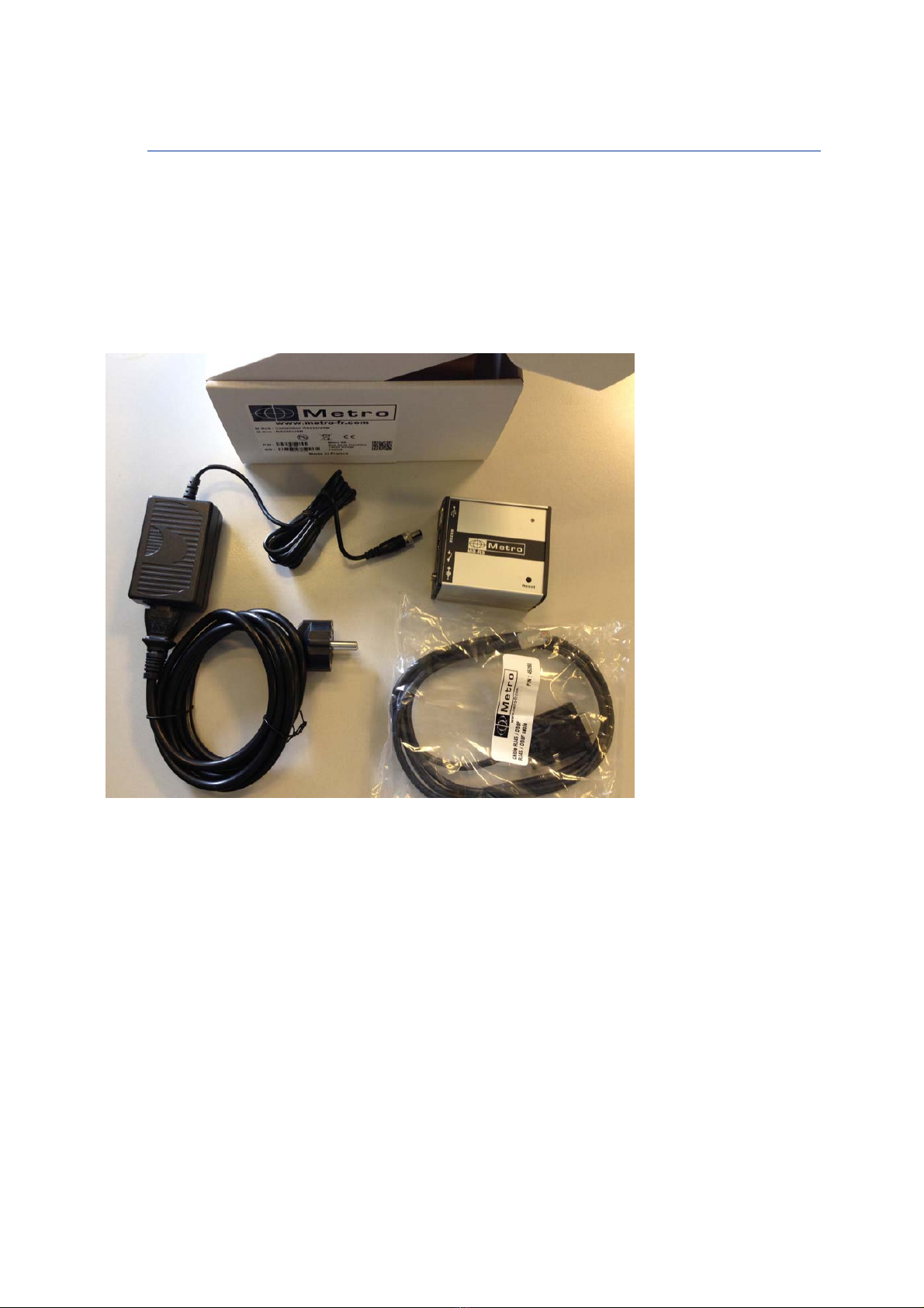
3.2.1. Contains of the packaging
The MB-IP package contains :
- 1 MB-IP module
- 1 USB cable
- 1 transformer + 1 power supply cable
- 1 Mini-CD including USB driver and this user manual

Version 1.0
4. CONNECTORS
USB Full-Speed with
ASCII protocol
(Creates a virtual
COM PORT)
Ethernet with ASCII or
modbus TCP.
RJ45 connector.
Footswitch input
Power supply
connector
12-30 VDC
Reset button

4.1. THE USB FULL-Speed CONNECTOR
This section is useful to setup the IP address of the module, or if you intend to use the MB-IP
with the USB connection.
Connecting the MB-IP on the computer with USB will create a virtual COM Port.
Follow the following instructions before using the MB-IP :
1- Launch the file « driver USB.exe » located in the directory « Driver USB » on the mini-
cd.
2- Connect the MB-IP to your computer through the USB cable, a with the power supply.
The following message appears few seconds after:
3- A COM PORT (USB SERIAL PORT) appears in the device manager menu.
(Configuration panel Device manager Ports (COM & LPT)
You can then note the COM port number. It can be useful later for the configuration of
your acquisition software.

Version 1.0
5. COMMUNICATION - ASCII PROTOCOL
The ASCII protocol allows to identify the modules on the bus, to read individually the
probes, to read the inputs status of an I/O module, to write on a output of an I/O
module etc…
All the commands ends by <CR> (Ascii $0D)
5.1. Network setting : IP address, mask and gateway setup
To enable the Ethernet communication, The IP address of the computer has to be
specified to the module. The USB link is firstly used to set the correct IP address.
The following commands allows to set the IP address and networks parameters :
IP address:
o Command : @IP=XXX.XXX.XXX.XXX<$0D> with XXX.XXX.XXX.XXX
= IP address of the MB-IP like 192.168.001.001
Subnet mask:
o Command : @MK=XXX.XXX.XXX.XXX<$0D> with XXX.XXX.XXX.XXX
= subnet mask address of the MB-IP like 255.255.255.000
Gateway:
o Command : @GW=XXX.XXX.XXX.XXX<$0D> with
XXX.XXX.XXX.XXX = Gateway address of the MB-IP like
192.168.000.001
From this moment, the Ethernet communication is available.
5.2. Identification of the M-Bus modules
Before reading the probes, it is necessary to identify the connected modules on the
MB-IP. This has to be done only the first time.
Up to 254 input can be connected. The address of the input will thus be from 00 to
FE.
Identify a module:
o Command : @NY=XX<$0D> with XX = address of the first channel in
hexadecimal
o Move the first probe of the module or press the ID button depending on
the module you use.
Tabla de contenidos
Otros manuales de Unidad de control de Metro DataVac


Manuales populares de Unidad de control de otras marcas

Festo
Festo Compact Performance CP-FB6-E Manual de lista de piezas

Elo TouchSystems
Elo TouchSystems DMS-SA19P-EXTME Manual de usuario

JS Automation
JS Automation MPC3034A Manual de usuario

JAUDT
JAUDT SW GII 6406 Series Guía rápida

Spektrum
Spektrum Air Module System Manual de usuario

BOC Edwards
BOC Edwards Q Series Manual de usuario


