Mercury SCC-1 Manual de usuario

SCC-1 SMARTCRAFT CONNECT GATEWAY
INSTALLATION MANUAL
IMPORTANT:This document guides our dealers, boatbuilders, and company service personnel in the proper installation
or service of our products. If you have not been trained in the recommended servicing or installation procedures for
these or similar Mercury Marine products, have the work performed by an authorized Mercury Marine dealer technician.
Improper installation or servicing of the Mercury product could result in damage to the product or personal injury to
those installing or operating the product. Always refer to the appropriate Mercury Marine service manual for component
removal and installation instructions.
NOTE:
After completing installation, place these instructions with the product for the owner's future use.
Components in Kit
NOTE:The termination band on the 10‑pin connector cable only applies to engine‑mounted modules.
a - SmartCraft CONNECT module
b - SmartCraft CONNECT module ‑ side view
c - Cable ties ‑ 4
d - #10 x .88" stainless steel wood screw
Features
The CAN P, CAN H, and NMEA lights will turn on when data is being transmitted through the gateway.
NOTE:This manual covers the installation of CAN P only ‑ engine‑mounted module (single). The helm‑mounted module
will default out of the box with CAN P and CAN H. CAN H is applicable to dual, triple, and quad DTS engine applications.
CAN H must be turned off if issues with the analog tachometers are encountered on mechanical/non‑DTS products.
a
b
c
d
71911
TERMINATED
ENGINE MOUNT ONLY
90-8M0219240 eng MAY2023 © 2023 Mercury Marine Page1 / 23
8M0219240 523 eng

NOTE:At the time of this publication, VesselView Link and SmartCraft CONNECT cannot be used together on the same
network.
SmartCraft CONNECT Module—Single through Quad‑Engine
NOTE:The SmartCraft CONNECT module does not provide power for any device on the NMEA 2000 network. The NMEA
2000 network will require its own power source. The NMEA 2000 network power input must have appropriate circuit
protection for the devices on the NMEA 2000 network.
NOTE:The termination band on the 10‑pin connector cable only applies to engine‑mounted modules.
a - CAN P connection light
b - NMEA connection light
c - CAN H connection light
d - Wi‑Fi connection light
e - Bluetooth® connection light
f - NMEA 2000® connector
g - 10‑pin connector
Module Harness Connections
1. Connect the SmartCraft CONNECT module in one of the two following ways:
a. Connect the CAN 10‑pin harness connector to the SmartCraft junction box. Refer to the following diagram.
b. Connect the CAN 10‑pin harness connector to the helm harness SmartCraft 10‑pin connection using a male‑male
adapter harness.
TERMINATED
ENGINE MOUNT ONL
Y
a
b
d
e
c
f
g
71912
SCC-1 SMARTCRAFT CONNECT GATEWAY INSTALLATION MANUAL
Page2 / 23 © 2023 Mercury Marine 90-8M0219240 eng MAY2023

2. Connect the module NMEA 2000 harness connector to the NMEA 2000 network. A NMEA 2000 extension may be
required to reach the NMEA 2000 backbone.
a - 120‑ohm termination resistor
b - Chartplotter
c - SmartCraft CONNECT module
d - NMEA 2000 fused power source
e - SmartCraft junction box
On‑Engine Mounting Guidelines
Mounting Requirements
NOTE:The 10‑pin on‑engine terminator must be removed from the engine harness before installation of the module.
• The SmartCraft CONNECT module must be mounted in a location that allows for connection to the 10‑pin connector on
the engine harness. No additional 10‑pin harnessing may be used in the installation of this product.
• All routing must adhere to harness installation bend parameter specifications. The minimum bend radius of any portion of
the harness must be no less than 13 mm (0.5 in.).
• Two cable ties to secure the SmartCraft CONNECT module must be used to prevent unwanted movement during normal
operation of the propulsion package.
•The following locations must be avoided when installing the SmartCraft CONNECT module.
• Any location which can be exposed to water
• Any location that is subject to high heat during operation of the power package
• Near ignition coils
• Near spark plug wires
• Near shift/throttle cables
• Where harnessing could contact belts
• Secured to fuel lines
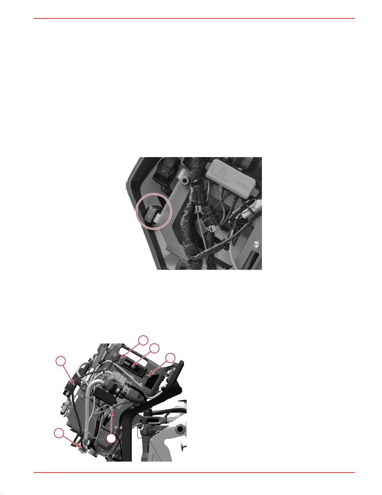
25/30 FourStroke EFI On‑Engine Mounting
1. Locate the SmartCraft 10‑pin connector and remove the CAN termination resistor. Connect the 10‑pin connector on the
SmartCraft CONNECT harness. On‑engine modules are internally terminated, so the termination resistor is no longer
needed.
75350
a
a
b
d
71914
e
c
TERMINATED
ENGINE MOUNT ONLY
SCC-1 SMARTCRAFT CONNECT GATEWAY INSTALLATION MANUAL
90-8M0219240 eng MAY2023 © 2023 Mercury Marine Page3 / 23

2. Route the harness behind the intake runner mounting tab and secure it with a cable tie.
75351
3. Locate the module mounting bracket on the engine and secure the module with two cable ties.
75352
4. This routing will keep the harness away from moving engine components.
75353
Typical SmartCraft harness routing path
5. The NMEA 2000 connector can remain capped, if it is not intended to be used.
Mercury Avator™ 7.5e Electric On‑Outboard Mounting
IMPORTANT:Mercury Marine strongly recommends that a trained and certified technician perform servicing tasks that
require removing cowling, including installing the SmartCraft CONNECT.
NOTE:Cowl removal and installation instructions can be referenced in the Mercury Avator 7.5e Operation and Installation
Manual.
NOTE: The following instructions are for installing the SmartCraft CONNECT on tiller models. The SmartCraft CONNECT
must be mounted under the helm on remote control models.
1. Record the serial number from the body of the SmartCraft CONNECT in the SN: space in the SmartCraft CONNECT
Serial Number table.
SmartCraft CONNECT Serial Number
SN:
2. Remove the battery from the outboard. Refer to the Mercury Avator 7.5e Operation and Installation Manual Battery
Removal.
SCC-1 SMARTCRAFT CONNECT GATEWAY INSTALLATION MANUAL
Page4 / 23 © 2023 Mercury Marine 90-8M0219240 eng MAY2023
IMPORTANT:Remove the Mercury Avator battery from the outboard motor before performing inspections, assembly,
maintenance, and repair activities.
• Only use the provided handles to carry the Mercury Avator battery.
• Keep the Mercury Avator battery away from children.
• Keep the Mercury Avator battery away from objects that may cause short circuits, like tools, screws, nails, watches,
bracelets, necklaces, keys, or other metal objects.
• Handle the Mercury Avator battery with care. Do not crush the Mercury Avator battery or subject it to mechanical shock.
• Keep the Mercury Avator battery away from sources of heat and fire.
• Do not place the Mercury Avator battery in the presence of flammable vapors or in flammable dust environments.
3. Remove the front cowl upper panel from the outboard. Refer to the Mercury Avator 7.5e Operation and Installation
Manual Front Cowl Upper Panel Removal.
4. Remove the front cowl lower panel from the outboard. Refer to the Mercury Avator 7.5e Operation and Installation
Manual Front Cowl Lower Panel Removal.
5. Remove the starboard cowl panel from the outboard. Refer to the Mercury Avator 7.5e Operation and Installation Manual
Starboard Cowl Panel Removal.
6. Remove and discard the weatherproof connector cover from the 10‑pin data harness connection.
76053
7. Connect the 10‑pin connector on the SmartCraft CONNECT to the outboard wiring harness connector.
8. Verify the connectors are connected by pulling on the connections.
NOTE:The connectors should be aligned and seated flush for a proper connection.
IMPORTANT:Do not secure the SmartCraft CONNECT to the main battery bracket assembly. The cable ties will
interfere with the battery.
9. Install the SmartCraft CONNECT on the outboard and secure the SmartCraft CONNECT harness to the outboard with
the cable ties.
a - SmartCraft CONNECT
b - Cable tie
c - SmartCraft CONNECT harness
d - 10‑pin connector
a
b
b
b
c
76061
d
SCC-1 SMARTCRAFT CONNECT GATEWAY INSTALLATION MANUAL
90-8M0219240 eng MAY2023 © 2023 Mercury Marine Page5 / 23

10. Install the starboard cowl panel on the outboard. Refer to the Mercury Avator 7.5e Operation and Installation Manual
Starboard Cowl Panel Installation.
11. Install the front lower cowl panel on the outboard. Refer to the Mercury Avator 7.5e Operation and Installation Manual
Front Lower Cowl Panel Installation.
12. Install the front upper cowl panel on the outboard. Refer to the Mercury Avator 7.5e Operation and Installation Manual
Front Upper Cowl Panel Installation.
13. Install the battery in the outboard. Refer to the Mercury Avator 7.5e Operation and Installation Manual Battery
Installation.
Module Configuration
IMPORTANT:For configuration of the SmartCraft CONNECT module, a mobile device and a Wi‑Fi connection with access to
the internet is required.
IMPORTANT:If using a SIMRAD® with NSX™ software, Garmin®, or a Raymarine® display, visit their websites to make
sure the display is running the latest software available.
Consumer Configuration Process
NOTE:Wireless‑only SmartCraft CONNECT module versions only need to complete the firmware update, and do not need to
go through the configuration steps. See
Mercury Dealer or OEM Configuration Process: Step 12
.
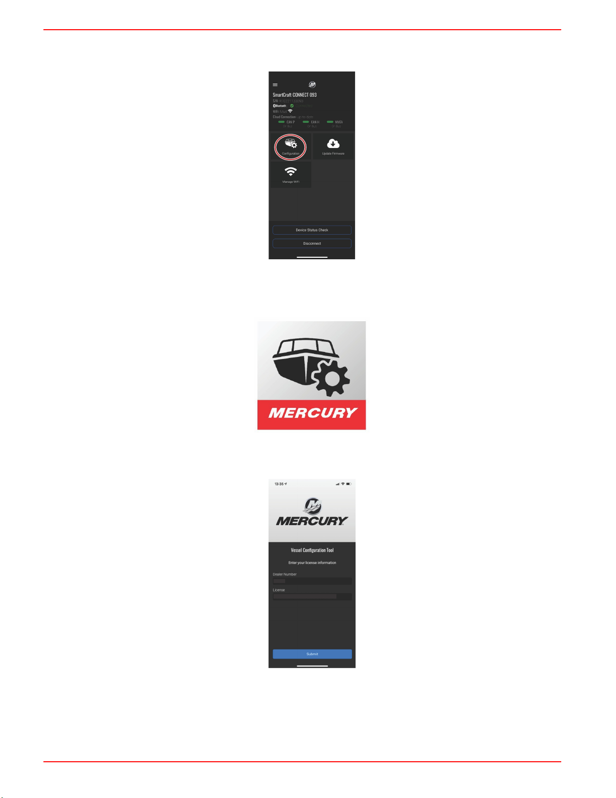
1. Download the SmartCraft Manager app from the iOS App Store or Google Play Store.
73578
2. After the app has been downloaded to the device, open the app to begin the configuration process.
3. Allow for Bluetooth® connectivity to use the configuration app.
75307
SCC-1 SMARTCRAFT CONNECT GATEWAY INSTALLATION MANUAL
Page6 / 23 © 2023 Mercury Marine 90-8M0219240 eng MAY2023

4. Select the consumer user option.
75308
5. Select Continue to begin data sharing.
75309
6. Enter the email address and password. As a first time user, select the Sign up now option.
75310
SCC-1 SMARTCRAFT CONNECT GATEWAY INSTALLATION MANUAL
90-8M0219240 eng MAY2023 © 2023 Mercury Marine Page7 / 23

7. Complete all of the required data fields. When finished, select the Create button.
75312
8. Power up the SmartCraft CONNECT and all other vessel components, select Find My Device. Select the SmartCraft
CONNECT device.
75314
75377
9. Enter the SmartCraft CONNECT serial number. This can be found on the side of the module, or by querying the list of the
NMEA devices on the vessel network, using an MFD display. After entering the serial number, select Save.
75315
SCC-1 SMARTCRAFT CONNECT GATEWAY INSTALLATION MANUAL
Page8 / 23 © 2023 Mercury Marine 90-8M0219240 eng MAY2023

10. Select the Wi‑Fi network that will be used for communication connection.
NOTE:Networks that do not require a password are acceptable to use. Captive portal Wi‑Fi networks, which require a
user to interact with a web page, cannot be used to configure this module.
NOTE:The device name uses the last 3 digits of the module serial number for identification.
NOTE:Wi‑Fi signal strength needs to be two bars to function properly.
72607
XXXXXXXXXX
11. Enter the password needed for establishing a connection to a Wi‑Fi network. Select Connect.
72608
12. After this data is entered, go to the Mercury Dealer or OEM Configuration Process: Step 11, to continue the
configuration process instructions.
SCC-1 SMARTCRAFT CONNECT GATEWAY INSTALLATION MANUAL
90-8M0219240 eng MAY2023 © 2023 Mercury Marine Page9 / 23
13. The SmartCraft CONNECT module can now be customized for vessel and engine data. The user input data will be stored
on the NMEA network. Changes can be made at any time to the vessel and engine configuration.
75317
Mercury Dealer or OEM Configuration Process
1. Download the SmartCraft Manager app from the iOS App Store or Google Play Store.
73578
2. After the app has been downloaded to the device, open the app to begin the configuration process.
3. Begin by entering the dealer number and license number.
XXXXXX
XXXXXX-OOOOOO-XXXXXX-OOOOOO-XXXXXX
72604
4. Sign in to the appropriate existing account with the email and password credentials. If this is the first time setting up a
SmartCraft CONNECT, an account must be created. Save the new account credentials for future use.
NOTE:Brunswick Corporation is moving all accounts to a single login. If you already have an account for 1st Mate,
Mercury University, MDA, Harris® boats, Boston Whaler®, Sea Ray®, etc., your username and password will work here.
SCC-1 SMARTCRAFT CONNECT GATEWAY INSTALLATION MANUAL
Page10 / 23 © 2023 Mercury Marine 90-8M0219240 eng MAY2023
Tabla de contenidos
Otros manuales de Puerta de Mercury


Manuales populares de Puerta de otras marcas

LST
LST M500RFE-AS Manual de usuario

Kinnex
Kinnex Media Gateway Manual de usuario

2N Telekomunikace
2N Telekomunikace 2N StarGate Manual de usuario

Mitsubishi Heavy Industries
Mitsubishi Heavy Industries Superlink SC-WBGW256 Manual de usuario

ZyXEL Communications
ZyXEL Communications ZYWALL2 ET 2WE Manual de usuario

Telsey
Telsey CPVA 500 - SIP Manual de usuario


