Mercury Sentry Manual de usuario

Sentry
Sentry I.S. Card Reader
User Manual

2017r0 Page 2 of 35 Sentry IS Card Reader User Manual
The following instructions relevant to safe use in a hazardous area apply to equipment covered by
certificate numbers Sira 99ATEX2138X.
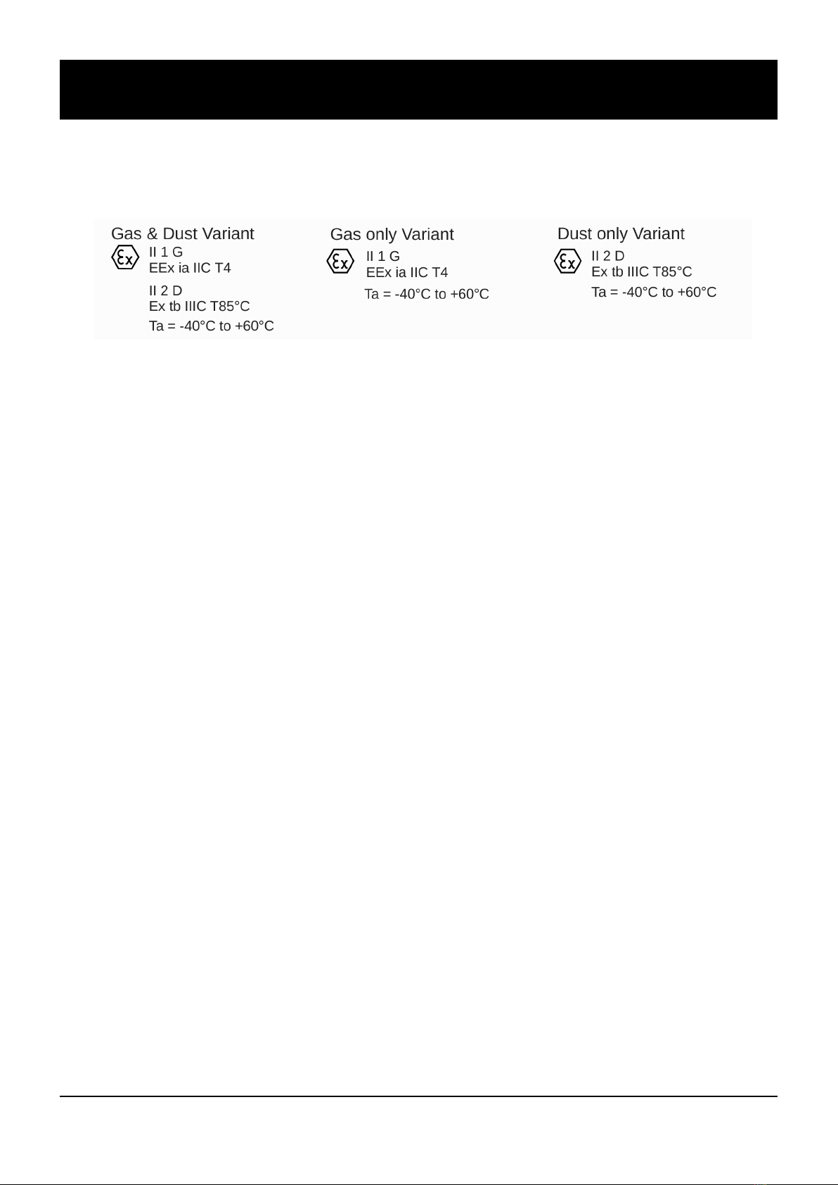
1. The certification marking is as follows:
Instructions Specific to Hazardous Area Installations
2. The equipment may be used in zones 0, 1 & 2 with flammable gases and vapours with apparatus groups IIA,
IIB & IIC and with temperature classes T1, T2, T3, T4.
3. The equipment may be used in zones 21 & 22 with flammable dusts, fibres and flyings in groups IIIA, IIB
and IIC, and temperature T85°C.
4. The equipment is only certified for use in ambient temperatures in the range 40ºC to +60ºC and should not
be used outside this range.
5. Installation shall be carried out in accordance with the applicable code of practice by suitablytrained
personnel.
6. There are no special checking or maintenance conditions other than a periodic check.
7. With regard to explosion safety, it is not necessary to check for correct operation.
8. The equipment contains no userreplaceable parts and is not intended to be repaired by the user. Repair of
the equipment is to be carried out by the manufacturer, or their approved agents, in accordance with the
applicable code of practice.
9. Repair of this equipment shall be carried out in accordance with the applicable code of practice
10. If the equipment is likely to come into contact with aggressive substances, e.g. acidic liquids or gases that
may attack metals or solvents that may affect polymeric materials, then it is the responsibility of the user to
take suitable precautions that prevent it from being adversely affected thus ensuring that the type of
protection is not compromised.
11. The certificate number has an ‘X’suffix which indicates that special conditions of installation and use apply.
Those installing or inspecting this equipment must have access to the contents of the certificate or these
instructions. The conditions listed in the certificate are reproduced below:
(i) Glass Fibre Reinforced Plastic (GRP) enclosure and parts of the aluminum enclosure are nonconducting and
may generate an ignitioncapable level of static under certain extreme conditions. The user should ensure
that the equipment is not installed in a location where it may be subjected to external conditions (such as
highpressure steam) which might cause a buildup of static on nonconducting surfaces. Additionally,
cleaning of the equipment should be done only with a damp cloth.
(ii) As painted aluminium is used at the accessible surface of this equipment, in the event of rare incidents,
ignition sources due to impact and friction sparks could occur. This shall be considered when the Sentry
Cardreader is being installed in locations that specifically require group II, category 1G equipment.

Sentry IS Card Reader User Manual Page 3 of 35 2017r0
Contact
Mercury HMI Ltd
George House
Derwent Road
Malton
North Yorkshire
YO17 6YB
UK
Tel: +44 (0) 1653 697 200
Fax: +44 (0) 8700 667 325
Email: [email protected]
Web www.mercuryHMI.co.uk
All trademarks are acknowledged as the property of their respective owners.
This document shall not form part of any contract. Specifications are subject to change without notice,
and Mercury HMI Ltd accepts no liability of any kind for errors or omissions.

2017r0 Page 4 of 35 Sentry IS Card Reader User Manual
Rev Date Changes
1.0 Original Release
1.1 Mercury IMC Version
2.0 27 Jul 09 Substantial revision of the manual for Wiegand O/P Mode, R507 barrier and
Modbus enhancements
2.1 6 Oct 09 All drawings redrawn
2.2 2 Dec 10 The Digital Output driving page 17 has been revised. Table boundaries
made finite thickness to help PDF printing
Extra reader type added
Config string updated
Links show Mercury HMI Limited & logo. Certificate checked.
2.3 18 Mar 11 Added Special conditions of use
2014r0 11 Nov 14 Substantial revision of the manual
Added GRP case information
Added LED cable orientation
Fixed Modbus coils
2015r0 1 Jul 15 Add Wiegand Output mode wiring diagram for Pepperl & Fuchs barriers
2016r0 29 Jul 16 Added Specific Conditions of use for Variation 5, including Dust to match
Issue 7 of the Sira 99ATEX2138X certificate
2017r0 7 Mar 17 Minor updates
Revision History

Sentry IS Card Reader User Manual Page 5 of 35 2017r0
Contents
Introduction........................................................................................................................6
System Overview.................................................................................................................6
Power / Comms Options......................................................................................................6
Base Unit............................................................................................................................. 6
Reader Types....................................................................................................................... 7
Enclosure Material...............................................................................................................7
Certification Standard...................................................................................................... 8
Installation..........................................................................................................................9
Overview............................................................................................................................. 9
Mounting the Sentry Card Reader.......................................................................................10
Weatherproofing.................................................................................................................. 10
Hazardous Area Connections...............................................................................................10
Twisted Pair Cabling............................................................................................................11
Safe Area Requirements...................................................................................................... 11
Safe Area Connections.........................................................................................................12
Internal Overview................................................................................................................12
Operation............................................................................................................................13
Power On.............................................................................................................................13
Set Up & Configuration.......................................................................................................14
Configuring the Reader Card Type......................................................................................14
Operating Mode...................................................................................................................15
Configuration String............................................................................................................16
Example Configuration String.............................................................................................17
Telemetry Block Structure................................................................................................18
Multi Drop...........................................................................................................................18
Data Only.............................................................................................................................18
Escape Sequences................................................................................................................19
Card Data ............................................................................................................................19
System Options.................................................................................................................. 20
Option 1 : IS Sentry in Standalone mode...........................................................................20
Option 2 : IS Sentry in MultiDrop Mode........................................................................... 20
Option 3 : IS Sentry in Standard Modbus Mode................................................................. 21
Option 4 : IS Sentry in Mercury 2+ Modbus Compatibility Mode..................................... 23
Option 5 : Safe Area Sentry.................................................................................................24
Option 6 : Wiegand D1/D0 Output Mode........................................................................... 25
Hazardous Area I/O............................................................................................................. 26
Appendix A Wiring Diagrams...........................................................................................27
Appendix B Specifications................................................................................................34
Appendix C Link Settings.................................................................................................35

2017r0 Page 6 of 35 Sentry IS Card Reader User Manual
Introduction
The Sentry Card Reader is a modular and highly configurable unit
designed to read a variety of different card types in Hazardous
Areas.
A complete Sentry Card Reader unit comprises of three main
components, and there are several versions of each of these main
components:
•A power and communications safety barrier, or galvanic
isolator, mounted in the Safe Area when the Sentry Card
Reader is to be used in a Hazardous Area installation.
•The Sentry base unit, with the processing and
communications electronics affixed in the Hazardous Area,
connected to the fixed wiring.
•The Sentry lid, containing the appropriate reader head (the
reader electronics and a safety barrier encapsulated together
into a module mounted behind the RF transparent window)
and the status LEDs.
There are three power and communications types available:
•For a Safe Area Sentry, the unit can be connected directly to
a power source and the communications can be connected
directly to a PC, PLC or DCS as needed.
•For a Hazardous Area Sentry, requiring serial
communications within the Safe Area, then an R507
Interface Module is needed.
•If Wiegand D1/D0 communications is needed from a
Hazardous Area mounted Sentry Card Reader, then a Safe
Area mounted P510 Module together with a pair of standard
zener barriers is needed. Mercury HMI recommend the use
of MTL or Pepperl and Fuchs barriers, but other
manufacturers can be accommodated.
There are then three variants of the Sentry base units:
•Safe Area Serial Communication version. This requires a
clean 24V power supply and provides RS422 or RS485
communications.
•Hazardous Area Serial communications version, supporting
point to point, multidrop and Modbus communications. An
R507 Interface Module will be required in the Safe Area.
•Hazardous area Wiegand Output Version. A Wiegand Output
kit comprising of a P510 Module and barriers is also needed.
Base Unit
System Overview
Power / Comms
Options

Sentry IS Card Reader User Manual Page 7 of 35 2017r0
The Senrty reasder supports several differents types of proximity
card technology:
•EM4001/4100
•MIFARE
•HID Prox (125kHz)
•AWID26/32
•HITAG
•SafeProx this is a "secure" 125kHz card technology
designed for use with the Mercury HMI products.
Support for new card types is ongoing, so please contact Mercury
HMI to enquire about any unlisted formats.
Note : the Sentry reader is only able to read the factory
programmed serial number (UID) from proximity cards. For cards
that allow user data to be stored on them (e.g. Mifare), the reader is
not able to retrieve this user information.
The Sentry can be provided with either a powder coated,
passivated aluminium housing, or a static dissipative GRP housing,
perfect for marine and salty environments.
Note that the dust variants can only be supplied in the GRP
housing.
Illustration 1 : Sentry Card Reader
Reader Types
Enclosure Material

2017r0 Page 8 of 35 Sentry IS Card Reader User Manual
Certification Standard
The SIRA certification No. 99ATEX2138X shows EEx ia IIC T4
for gas and Ex tb IIIC T85ºC, which is made up as follows:
EEx = European certificate for Hazardous Areas.
ia = Intrinsically Safe for Zone 0, continuous
Hazardous vapours.
IIC = Safe for ALL gas groups.
T4 = Component surface temperature cannot exceed
135°C.
Ex = Hazardous Area Product.
tb = Dust ignition protection by enclosure for Zones 21
and 22.
IIIC = Safe for ALL gas groups.
T85ºC = Component surface temperature cannot exceed
85°C.
The “Conditions of Certification”show the maximum parameters
of each of the input/output terminal blocks.
In this manual, ASCII single characters which are either control or
nonvisible codes (Hexadecimal 00H 1FH, 20Hand 7FH) are
indicated by enclosure in <>, for example, <ESC>.
Character strings which are indivisible sequences are shown
between quotation marks, for example, "<ESC> [ 2 J".
In the ASCII 7 and 8 bit code sets used by the Sentry Card Reader,
a character is represented by two digits, each in the range
hexadecimal 0 to F. For example, <SP>, the space character is
defined 20H.
Nomenclature &
Conventions
ATEX Number

Sentry IS Card Reader User Manual Page 9 of 35 2017r0
Installation
Illustration 2 : Sentry Mounting Hole Centres
The Sentry Card Reader has ATEX approval for use in Hazardous
Areas when used with the R507 Interface Module or a direct
equivalent.
The Intrinsically Safe Interface Module provides galvanic isolation
between the 24V D.C. power & host communication ports and the
I.S. Hazardous Area connection.
These connections to the Sentry allow a cable length of up to 1km
(when used with an R507) or 500m (when in Wiegand D1/D0
mode). The R507 communication ports provide for RS232 and
differential transmit and receive terminals for RS422/485, with tri
state control.
The Sentry should be ordered as a complete unit comprising base
unit and appropriate lid as required. The Sentry can then be
mounted on any convenient flat surface using the four holes
provided.
The dimensions of the box are shown in the diagram below.
Installation
Overview

2017r0 Page 10 of 35 Sentry IS Card Reader User Manual
To affix the Sentry Card Reader to a surface, prepare by drilling
four holes 204 mm apart in width and 82 mm apart in height, refer
to Illustration 2. Carefully remove the Sentry Lid containing the
reader head and LEDs, supporting the lid so that the cables are not
put under strain. If this is not possible, carefully remove reader
head plug from J2 (see Illustration 4) and the LED assembly plug
from J1 and store the reader head safely.
Four mounting screws can now be used to attach the Sentry Base
Unit to the mounting surface.
Now plan how the hazardous area wiring is going to be terminated.
For a simple IS installation, when the only connections are the 4
wires to the Sentry, use the left hand gland.
The Sentry Card Reader is weatherproof, but care must be taken to
ensure the “O”ring seals are in place and free from grit when
mounting the equipment.
In salty or corrosive areas, it is advisable to grease the lid screws to
avoid binding. Alternatively, the GRP enclosure may be a better
choice as it offers better protection, especially in marine
environments.
There are three 20mm threaded holes provided in the box for cable
glands. Two gland holes are provided with blanking plugs, the
other gland must be provided by the customer.
In its most basic configuration, Sentry wired to host, only one
cable is needed (See Appendix A drawing number P174’112 and
P174'113).
For hazardous area applications, the cable connecting the R507
power and communications interface needs to comply with the
following parameters:
Loop Resistance 40 ΩMaximum
Capacitance 142 nF Maximum
L/R Ratio 33 μH/ΩMaximum
Inductance 0.6 mH Maximum
In practice these parameters are easily met by standard cables;
e.g. a 1 mm2quad cable has approximately the following
parameters:
Loop Resistance 38 Ω/km Maximum
Capacitance 55 nF/km Maximum
L/R Ratio 2.5 μH/ΩMaximum
Inductance 0.48 H/km Maximum
For a cable length of 1km, this would satisfy safety and operating
requirements.
Weatherproofing
Hazardous Area
Connections
Mounting
the Sentry
Tabla de contenidos