Meech 200 Series Manual de usuario

Model 225
Operating
Manual
Ionising Blower


Products shown in this document may be covered by one or more patents, patents applied for
and/or registered designs and/or trade marks. For further information please refer to our Head
Oce or visit www.meech.com.
© Meech Static Eliminators Ltd., 26.10.2017
Contents
Introduction 3
Installation and Use 4
Front Panel Features 4
Indicator LED’s 5
Periodic Maintenance 8
Calibration 8
Repairs And Warranty 11

3
Introduction
The Model 225 has been designed and developed to meet the demanding
requirements of the electronic and pharmaceutical industries. It combines fast
static charge removal with highly balanced ion output. The charge decay and ion
balance performance of the 225 combined with its quiet operation, low particulation
and minimum maintenance requirements make the unit ideal for electronic ESD
applications.
Unpacking And Inspection
The Model 225 Ioniser has been carefully packed at the factory in a container
designed to protect it from accidental damage, dust and contamination. Nevertheless,
we recommend careful examination of the carton and contents for any damage. If
damage is evident, do not destroy the carton or packing material and immediately
notify the carrier of a possible damage claim. Shipping claims must be made by the
consignee to the delivering carrier. Meech Static Eliminators should be notied of any
claims.
Description
The Meech Model 225 is a powerful ionising blower that uses sophisticated electronics
to maintain a highly balanced ion output with long-term stability. Visual indicators and
an audible alarm warn the operator if the unit goes out of balance or if ion production
falls below acceptable limits due to dirty pins. An optional auto-shutdown function is
also provided to protect the work area in the event of a unit malfunction.
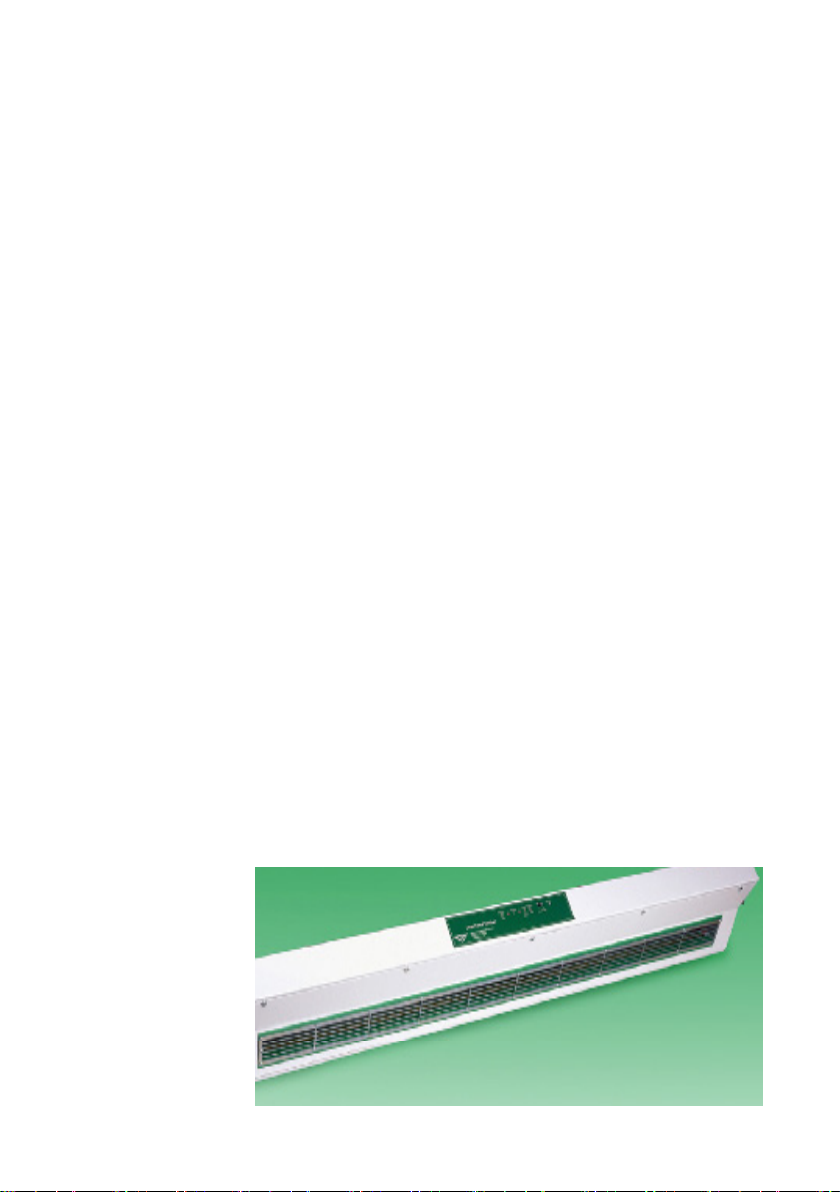
Model A225-1200
4
Installation and Use
The Model 225 Ioniser is designed for under-shelf mounting. Swivel mounting
brackets allow the unit to be rotated and clamped so that the ion airstream can be
directed over the required work bench area.
The mains supply is connected to the ioniser via its IEC ( the mains supply must
be elctrically grounded / earthed.) socket located on the rear of the blower. The
IEC socket of the blower incorporates the blower's main ON / OFF switch. The unit
contains an internal switch mode and thus will operate from mains voltages of 95-265
Volts AC at frequencies between 47-63Hz.
An earthing post on the rear panel of the Ioniser may be used to connect the unit’s
enclosure to the same potential as the anti-static workbench.
During normal operation of the Ioniser, care should be taken not to upset the ion
balance by touching the grill or allowing any object to come into contact with it.
WARNING - High voltages are present in the unit.
Qualied / Authorised personnel only
Under no circumstances should the unit be opened without rst turning o the
power and isolating the unit by disconnection of the power cord. Operators
must not try to insert ngers or any other object through the grill apertures.
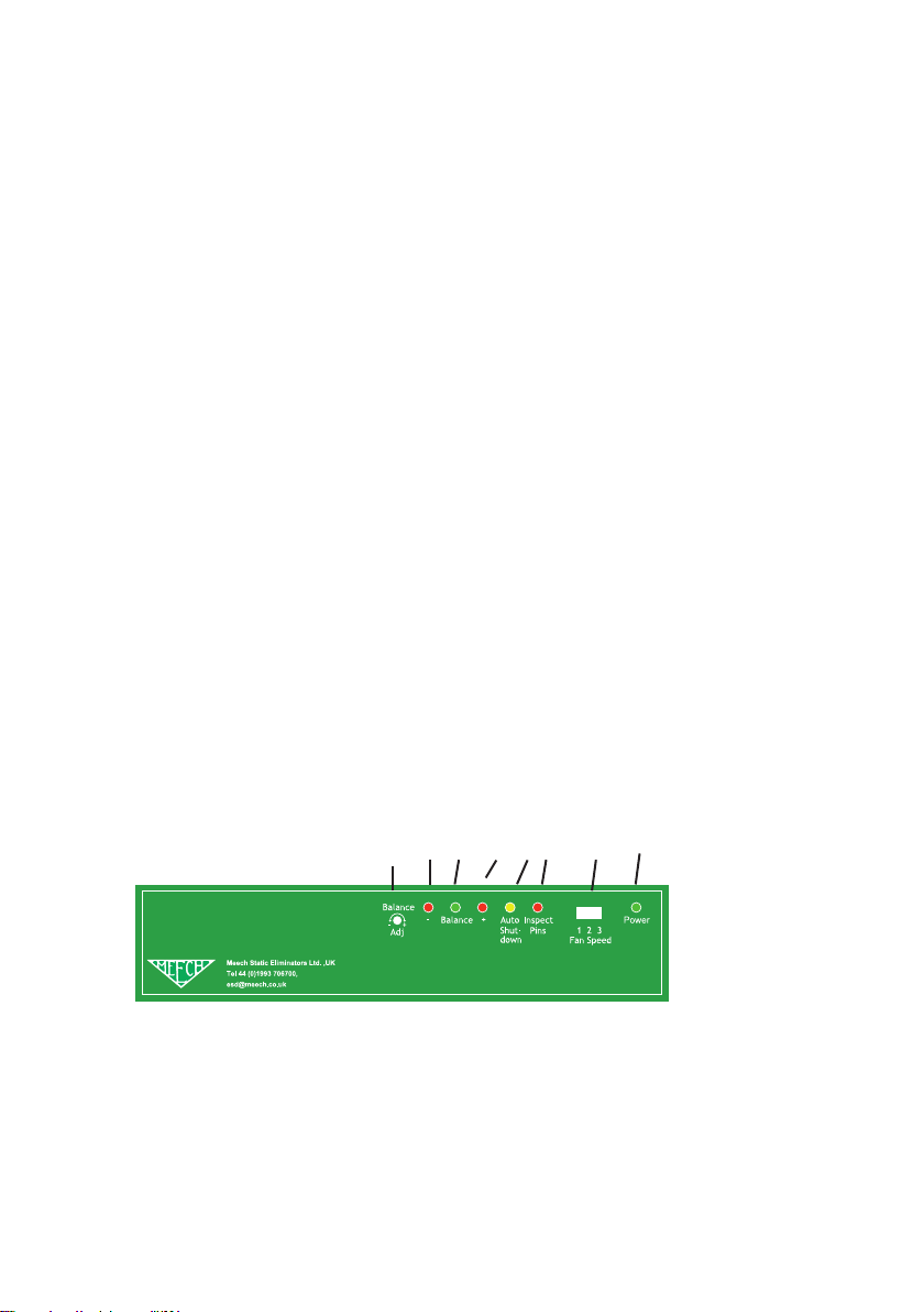
Front Panel Features
The front display panel of the Model 225 features six indicator LED’s and one ion
balance adjustment potentiometer (POT).
225Ionising Blower
5 2a 2b 2c 4 3 6 1

5
Indicator LED’s
1. Power On LED (Green)
This illuminates when the unit is switched ON and indicates that an electrical supply is
present within the Ioniser.
2. (a, 2b, 2c) Ion Balance Indicator LED’s ( Red, Green,
Red)
This array of three lamps indicates the ion balance state. Under normal operating
conditions only the middle (Green) lamp will be illuminated. This indicates that the ion
output from the ioniser is balanced. If the ion emission becomes imbalanced and the
imbalance exceeds the alarm limits (standard factory setting +/- 25V) then the green
lamp will dim or extinguish and either the positive (+ve) red LED or the negative (-ve)
red LED will illuminate dependant upon the polarity of the out of balance condition (
see “Fault Finding” later).
3. Inspect Pins (Red)
This lamp only illuminates when the emitter pins of the ioniser have become dirty and
the ion output has fallen below a factory pre-set level. i.e. when insucient ionisation is
being created to fully maintain optimum performance.
4. Auto Shutdown (Orange)
In normal operation this lamp will not be illuminated. The lamp will only illuminate when
the unit has detected a fault and the appropriate Selectable Diagnostic Functions have
been selected ( see “Alarm Function” later). When the lamp is illuminated, the HV
supply to the emitter pins will have been automatically switched o by the control circuit
of the ioniser. The ioniser fans and other indicator lamps will remain ON. Ion Balance
Adjustment

6
Ion Balance Adjustment
5.Ion Balance Adjustment POT
Balance adjustment is achieved via the recessed potentiometer. Turning this
potentiometer will increase or decrease the +ve or –ve ion output resulting in a
change in ion balance at the target surface .
Fan Speed Selection
6. Fan Speed Selection Switch
The fan speed can be selected using the fan speed selector switch on the
front panel of the blower. In this mode the fan speed can be adjusted to
one of 3 positions: high, medium and low.
Rear Sockets
7. Mains Input Socket with illuminated rocker switch
Connection of the mains supply via an IEC plug and cable (supplied) is at this point.
The electrical supply must be earthed / grounded. The rocker switch on the IEC socket
provides the Main ON/ OFF switch for the Blower.
8. RJ11 Socket
The RJ11 socket provides a means for an external ioniser controller to be attached to
the Model 225. (see “Specication” for wiring instructions).
7 9 8 10

7
9. RJ45 Socket
This socket provides output signals so that the Model 225 may be monitored remotely
by a Factory Management System (FMS) or similar. ( see specication for wiring
instructions).
10.Calibration trim POTS
Used for factory calibration
Alarm Function / Selection ( found on blower PCB)
11. Alarm Selection DIP switch
The DIP switch enables various alarm functions to be set - typically sounding of an
internal audible alarm and auto shut down functions in the event of either out of
balance and / or inspect pins alarms .
12. Calibration / Normal Operation Jumper
This jumper selects either normal operation mode or calibration mode. In calibration
mode some functionality of the blower is disabled.
12
11

8
Periodic Maintenance
The periodic maintenance required by the unit will depend on the amount of dust or
contaminants in the operating environment. The high voltage emitter pins and grill
will typically require monthly cleaning. However, the optimum frequency of cleaning
will depend upon the operating environment and the number of hours of operation.
Periodic cleaning should not be postponed until the Inspect Pins lamp becomes
illuminated. However if the Inspect Pins lamp does illuminate then the unit should be
cleaned as soon as possible.
Touching or cleaning of the emitter pins or grill should only be performed with
the unit turned o and isolated from the electrical supply.
Access to the pins is achieved by removing the door retaining screws and hinging
it open. Cleaning of the pins and grill should be carried out using a cotton swab
dampened in isopropanol. Operators should avoid touching the pins with their ngers
as they are very sharp.
The emitter pins must be allowed to dry before the unit is switched back on
(typically 5 minutes)
If the pins are found to be worn and require replacement, the pins should be removed
using a pair of round nose pliers and replacements tted. Replacement pins are
available from Meech.
Calibration
This should be completed by Authorised Personnel only
The Model 225 has been factory calibrated in accordance with ANSI-EOS/ESD-
S3.1-1991. to achieve a maximum balanced ion output in standard applications. It is
calibrated using a charge plate monitor at maximum fan speed with the charge plate
450mm from the blower grill.
Otros manuales para 200 Series
3
Este manual sirve para los siguientes modelos
1
Tabla de contenidos
Otros manuales de Soplador de Meech


