
Maxxus 4.2 Instrucciones de instalación

ENG
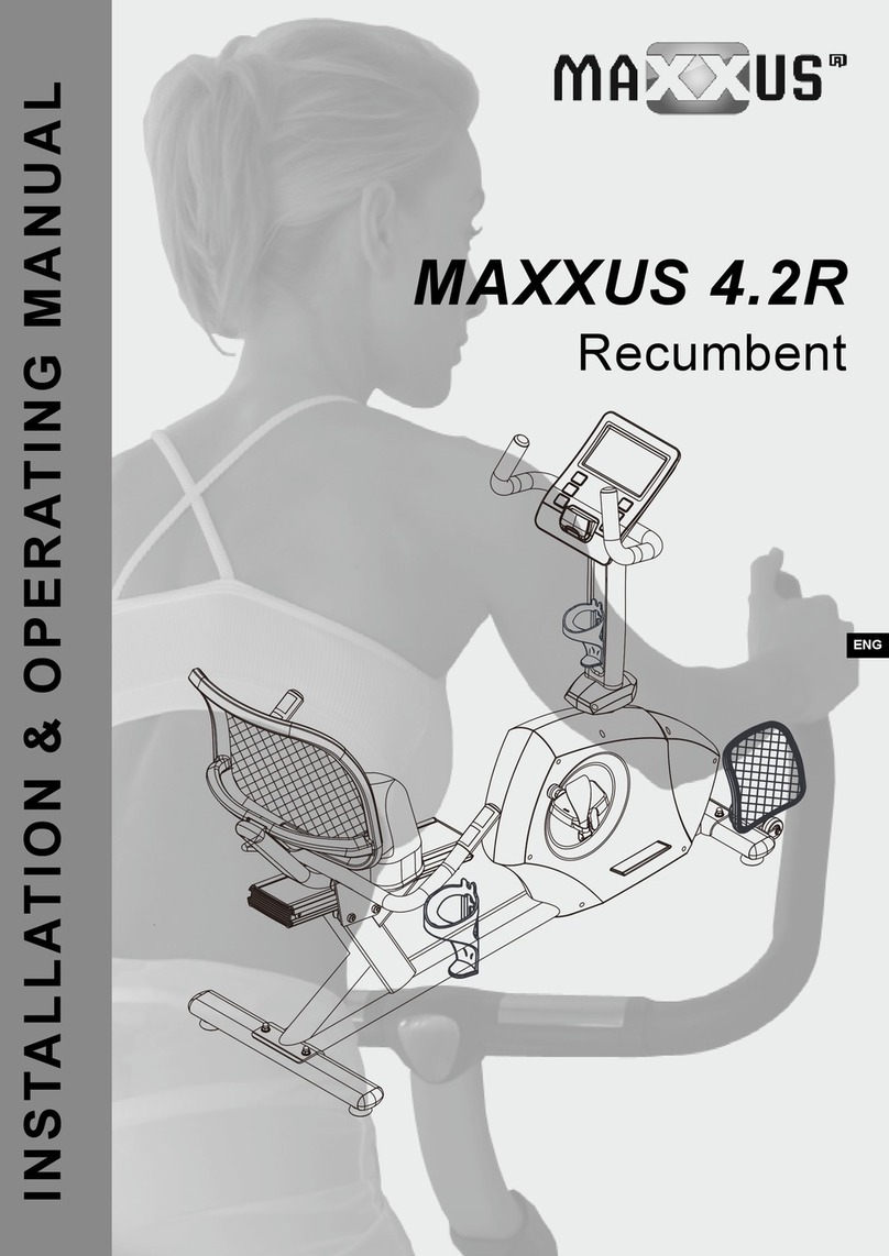
MAXXUS 4.2
Bike
INSTALLATION & OPERATING MANUAL

2
Index
Index 2
Safety Instructions 3
Overall View of the Device 4
Scope of Delivery 4
Fastening Materials 5
Tools Included in Delivery 5
Assembly 6 – 10
Seat Adjustment 11
Levelling 11
Transport, Location & Storage 12
Care, Cleaning & Maintenance 12
Mains Connection 13
Cockpit 14 – 21
Pulse & Heart Rate 22 – 23
Training Recommendations 24 – 25
Technical Details 26
Disposal 26
FAQ 27
Recommended Accessories 27
Exploded Drawing 28
Spare Parts List 29
Warranty 30
Service Contract 31
© 2019 MAXXUS Group GmbH & Co. KG
All rights reserved / All rights reserved
This publication may not be reproduced, stored in a retrieval system, or transmitted in whole or in part, in any form or by any means, electronic,
mechanical, photocopying, recording, or otherwise without the prior written permission of Maxxus Group GmbH & Co. KG.
Errors, colour and technical modication subject to change, reproduction as well as electronic duplication only with written permission of MAXX-
US Group GmbH & Co. KG.
3
ENG
Safety Instructions
Before you start exercising, be sure to read the entire operating manual, especially the Safety Information, the Maintenance
and Cleaning Information and the Training Information. Also make sure that anyone else who uses this training device is famil-
iar with this information and observes it.
Always follow the maintenance and safety instructions in this manual very carefully.
This training device may only be used for its specic intended use. Any misuse can cause risk of possible accident, damage to
health or damage to the device for which the Distributor will not assume any liability.
Electrical Connection (only applies to devices with an external electrical connection)
−A mains voltage of 220-230V is required to operate this training device.
−The training device is only to be connected to the mains with the mains cable supplied using a 16A individually fused and
earthed socket installed by a qualied electrician.
−Always remove the electric plug from the socket before moving the training device.
−Remove the electric plug from the socket before commencing any cleaning, maintenance or other works.
−Do not connect the mains plug to a socket on a socket strip or on a cable drum.
−If using a cable extension please ensure that this complies with DIN standards, VDE regulations and guidelines, technical
rules issued by other European Union states.
−Always place the mains cable so it cannot be damaged or cause a tripping hazard.
−In operating or standby mode, electrical devices such as mobile phones, PCs, Televisions (LCD, plasma, tube, etc.), game
consoles etc. will emit electro-magnetic radiation. For this reason, all these types of devices should be kept away from
your training device as they could lead to malfunction, disturbances or false outputs being shown in heart rate measure-
ments.
−For safety reasons, always remove the electrical plug from the socket when the device is not in use.
Training Environment
−Select a suitable space for your training device to provide an optimum amount of free space and highest level of safety.
You should leave a safety distance of at least 100 cm behind the training device and at least 100cm to each side and in
front of the device.
−Make sure that the area is well ventilated and that an optimum amount of oxygen is available during training. Avoid
draughts.
−Your training device is not suitable for outside use and so storage and training can only take place in a temperate, clean
dry room.
−The temperature range to operate or store this device is between a minimum of 10° and maximum of 30°
−Do not operate or store your training device in wet areas such as in swimming pools, saunas etc.
− Make sure that your training device is kept on at, hard, clean ground both in operation and at rest. Any uneven surfaces
must be removed or made good.
− It is recommended permanently to place a MAXXUS® Floor Protection Mat under the device to protect damageable oors
such as wood, laminates, oor tiles etc. Please ensure that the mat cannot slip or slide.
−Do not put this training device on pale or white coloured carpets or rugs as the feet of the device may leave marks.
−Make sure that your training device and mains cable are kept out of contact with hot surfaces and are kept at a safe dis-
tance from any sources of heat e.g. central heating, hot stoves, furnaces, ovens or open res.
Personal Safety Instructions for Training
−Remove the mains cable from the training device when not in use to avoid inappropriate or uncontrolled use by any other
third party, e.g. children.
−You should have a health check carried out by your doctor before you start any training
− Stop training immediately if you feel physically unwell or are experiencing any breathing diculties.
−Always start your training session at a low workload increasing it slowly but steadily throughout. Reduce the workload
again towards the end of your training session.
−Suitable sports shoes and clothes should always be worn during training sessions. Make sure that loose clothes do not
get caught up in the treadmill belt or rollers.
−Your training device is only to be used by one person at a time.
−Check each time before a training session to see if your device is in perfect condition. Never use your training device if it is
faulty or defective.
−You are only permitted to carry out repairs to the device yourself after having contacted our Service Department and on
receipt of explicit permission to do so. Only original spare parts may be used at any time.
−Your training device must be cleaned after each use. Remove all dirt including body sweat or any other liquids.
−Always make sure that liquids (drinks, body sweat, etc.) do not get onto the vibrating plate or into the cockpit as this can
cause damage to the mechanical and electronic components.
−Your training device is not suitable for use by children.
−Third parties, especially children and animals, must be kept at an appropriate safety distance during training.
−Check if there are any items underneath the training device before each training session and remove them without fail.
Never use the training device when items are underneath it.
−Do not allow children to use your training device as a toy or climbing frame at any time.
−Ensure that no body parts of your own or of third parties ever come in contact with any of the moving mechanisms.
The construction of this training device is based on state-of-the-art technology and highest modern technical safety standards.
This training device is to be used by adults only! Extreme misuse and/or unplanned training can cause damage to your health!
This training device is suitable for non-therapeutic purposes.

4
Overview of the Device
Scope of Delivery
A C
B
D E F
G H I J K
Handlebars
Pulse sensors
Seat
Mains Adapter Connection
Pedal
Cockpit
Handlebar Shaft
Stand with Transport Rollers
Stand
Item Description Qty
A Base Frame 1
B Stand, front 1
C Stand, rear 1
D Handlebar Shaft 1
E Handlebars 1
F Pedals 2
Item Description Qty
G Bottle Holder 1
H Handlebar Shaft Cover 2
I Seat 1
J Cockpit 1
KMains Adapter, 9V 1

5
ENG
Fixing Materials
Tools Included in Delivery
12311
4 8 9 12
B36
5 7 B37
Item Description Qty
7Combi Tool 1
5 Allen Key, M5 1
B36 Washer for B37 1
B37 Locking Bolt 1
Tools may be supplemented or replaced with your own. Make sure that they are an
accurate t.
Item Description Qty
1 Washer, 3/8" 8
2 Hex Bolt, 3/8" 4
3 Hex Bolt, M8x25 4
4 Allen Bolt, M8x25 2
8 Cap Nut, 3/8" 4
9 Self Tapping Screw, M5 2
The following screws and bolts come preassembled
Item Description Qty
11 Pan Head Screw 4
12 Allen Bolt, M5 2

8
1
CA
2
6
Carefully unpack all parts of the delivery. Two people are required because some parts of your training device
are bulky and heavy. Before starting the assembly, check the completeness of the xing materials (screws, nuts,
etc.) and the components against the parts and xing material lists on the previous pages of this manual.
Carefully carry out the installation, as damage or defects that have arisen due to assembly errors are not
covered by the warranty under any circumstances. Read the instructions carefully before starting, follow the
sequence of the installation steps exactly and follow the instructions for the individual assembly steps. The
installation of the training device must be carried out by responsible adults.
Carry out the installation of your training device with two adults in a location that is level, clean and free of
obstruction during assembly. Only after assembly of the training device has been completed can training be
started.
Step 1: Assembling the Rear Stand
Attach the rear stand (C) with two 3/8” hexagon bolts (2), four 3/8” washers (1), and two 3/8” cap nuts (8) to the
rear mounting of base frame (A).
Assembly

8
B
1
2
A
D
A
3
7
ENG
Step 2: Assembling the Front Stand
Attach the front stand with transport rollers (B) with two 3/8” hexagon head screws (2), four 3/8” washers (1) and
two 3/8 “cap nuts (8) to the front mounting of the base frame (A).
Step 3: Assembling the Handlebar Shaft
Connect the end of the cable coming out of the bottom of the handlebar shaft
(D) to the end of the cable protruding from the base frame (A). Now place
the handlebar shaft (D) on the mounts on base frame (A) and x it with four
hexagon nuts M8 (3).
CAUTION:
When inserting and securing the handlebar shaft, make sure that you do not
crush or damage the cables.
Assembly

H
D
A
9
D
E
4
8
Step 4: Assembling the Handlebars
Pass the hand pulse measurement cable, coming out from the bottom of the handlebar (E), in through the
upper, front opening of the handlebar shaft (D) and then out from the upper opening. Now lead the two cables
(hand pulse measurement & connection cable) upwards from below through the opening in the handlebar (5).
Note:
Pull out the cables only as far as necessary to connect them to the cockpit later.
Now x the handlebar (E) with two Allen bolts M8 (4) to the handlebar shaft (D).
CAUTION:
When attaching the handlebar (E), be careful not to crush or damage the cables.
Step 5: Assembling the Handlebar Shaft Cover
Place the two parts of the handlebar shaft cover (H) on the right and left of the joint between the handlebar shaft
(D) and the base frame (A). Secure it with two self-tapping screws (9).
Assembly

GD
12
J
11
D
9
ENG
Step 6: Assembling the Cockpit
Loosen and remove the four pan head screws (11) preassembled on the back of the cockpit (J). Connect the
cables protruding from the cockpit (J) with the cables protruding from the handlebars. Carefully check the cable
connections. Carefully push the excess cables back into the handlebar shaft (D). Now secure the cockpit (J) to
the handlebar shaft with the four pan head screws (11).
CAUTION:
When attaching the cockpit (J) make sure that you do not crush or damage the cables.
Step 7: Assembling the Bottle Holder
Loosen and remove the two M5 Allen screws (12) on the handlebar shaft (D) and use them to attach the bottle
holder (G) to the handlebar shaft (D).
Assembly

I
B36
B37
A03
F
10
Step 8: Assembling the Seat
Attach the seat plate (I) to the adjustable bracket of the seat support (A03) with locking screw (B37) and washer
(B36).
Step 9: Assembling the Pedals
Insert the right pedal (F) thread into the right pedal arm socket and tighten it clockwise. Insert the left pedal (F)
thread into the left pedal arm socket and tighten it anti-clockwise.
Assembly
Otros manuales para 4.2
1
Tabla de contenidos
Otros manuales de Bicicleta estática de Maxxus

Maxxus
Maxxus SpeedBike S1 Instrucciones de instalación

Maxxus
Maxxus PRO SPK-23 Manual de usuario

Maxxus
Maxxus 4.2 Instrucciones de instalación

Maxxus
Maxxus 90R Pro Instrucciones de instalación

Maxxus
Maxxus AirBike 90PRO Instrucciones de instalación
Maxxus
Maxxus 4.2R Manual de usuario

Maxxus
Maxxus 4.2R Instrucciones de instalación

Maxxus
Maxxus RunMAXX 90 PRO Instrucciones de instalación

Maxxus
Maxxus 6.2 Instrucciones de instalación

Maxxus
Maxxus PRO SPK-21 Manual de usuario


